Draught fan for heating reactor main container

A main container, reactor technology, applied in the components of the pumping device for elastic fluid, machine/engine, mechanical equipment, etc., to ensure reliability and meet the effect of heat-resistant temperature

Pending Publication Date: 2019-11-05
CHINA INSTITUTE OF ATOMIC ENERGY
View PDF0 Cites 0 Cited by
  • Summary
  • Abstract
  • Description
  • Claims
  • Application Information

AI Technical Summary

Problems solved by technology

[0003] The purpose of the present invention is to provide a fan for heating the main reactor vessel, which not only needs to meet the gas heating and ventilation cycle of the main vessel, but also meets the function of temperature rise and heat preservation, so as to solve the problem of simultaneous heating of the main reactor vessel and reactor internals

Method used


Image

  • Draught fan for heating reactor main container
  • Draught fan for heating reactor main container
  • Draught fan for heating reactor main container

Examples


Embodiment Construction

[0017] The present invention will be described in detail below in conjunction with the accompanying drawings and embodiments.

[0018] The fan used for heating the reactor main vessel provided by the present invention is to connect the inlet and outlet of the fan with the reactor main vessel to form a closed loop, and the fan acts on the medium gas to increase the kinetic energy and internal energy of the medium gas, wherein the kinetic energy keeps the gas in the heating process. The gas circulation in the system pipeline can increase the temperature of the circulating medium gas. When the high-temperature gas flows in the main container and the interlayer of the protective container, the main container and its components are continuously heated to achieve the purpose of uniform temperature rise of the main container and its components.

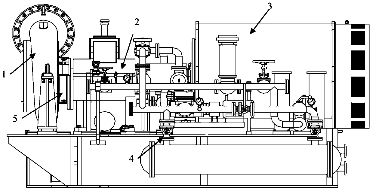
[0019] The fan structure is a single-stage high-speed centrifugal blower, such as figure 1 As shown, it is mainly composed of fan body 1, ...


PUM


Abstract

The invention relates to a draught fan for heating a reactor main container. The draught fan comprises a draught fan body, a gearbox, a coupling, a three-phase asynchronous motor, a thin oil station,a sealing device and a frequency speed control system. By means of the design of an inlet installation angle and an outlet installation angle of impeller blades, at least 75% mechanical energy can beconverted into heat energy, and the heating power not lower than 650 kW can be provided; and by means of the design of a volute cooling water loop and a heat insolation baffle, the working temperatureat the shaft sealing part is lowered, and the reliability of a sealing device is ensured. The draught fan solves the problem of simultaneous stable heating of the reactor main container and reactor inner components and can be applied and popularized to preheating of large container type equipment with complex inner structures.

Description

technical field [0001] The invention belongs to the design of a fan, in particular to a fan used for heating a reactor main vessel. Background technique [0002] The main container of the sodium-cooled fast reactor needs to be preheated in advance before filling with sodium, so as to reduce the thermal shock caused by the liquid metal sodium entering the main container to the inner wall of the main container and the internal components of the reactor. At present, the commonly used heating technology generally converts electrical energy into thermal energy, and then heats objects through contact heat conduction. This heating method is not suitable for large-scale container equipment that is not accessible inside and has a complex internal structure, and cannot meet the requirements for uniform temperature rise of internal and external structures, such as the main container of a reactor. The reactor main vessel includes the reactor body, reactor internals and protective vesse...

Claims


Application Information

Patent Timeline
Patent Type & Authority Applications(China)
IPC IPC(8): F04D25/08F04D29/28F04D29/30F04D29/58F04D29/42F04D29/02
CPCF04D25/08F04D29/023F04D29/281F04D29/30F04D29/4233F04D29/584F04D29/5853
Inventor 许业强杨红义余华金吴水金裴志勇吕明宇
Owner CHINA INSTITUTE OF ATOMIC ENERGY
Why Eureka
Try Eureka