
A high-temperature heat pipe working medium charging device and method

A high-temperature heat pipe and working fluid technology, applied in the field of heat pipes, can solve the problems of complicated operation, difficulty in measuring the filling amount of working fluid, affecting the purity of working fluid, etc., and achieves the effect of convenient operation, reducing the risk of pollution, and avoiding human contact.

Active Publication Date: 2020-10-09
GUILIN UNIV OF ELECTRONIC TECH
View PDF8 Cites 0 Cited by
  • Summary
  • Abstract
  • Description
  • Claims
  • Application Information

AI Technical Summary

Problems solved by technology

However, the filling process is carried out under high vacuum, and the temperature needs to be kept above the melting point of the working fluid, which makes it very difficult to measure the filling amount of the working fluid.
However, there are few studies on the method of charging high-temperature heat pipe working medium. For example, patents 201210378002.5 and 201410306757.3 are filled with a glove box structure. First, a certain amount of solid working medium is cut, weighed by a balance, heated and melted, and then rushed into the heat pipe
This method can only weigh the working fluid required by one heat pipe at a time, and the subsequent heat pipe needs to be re-cut and weighed, which is relatively cumbersome.
In addition, during the cutting process, impurities and moisture in knives, gloves, and inert gases affect the purity of the working medium.

Method used


Image

  • A high-temperature heat pipe working medium charging device and method

Examples


Embodiment 1

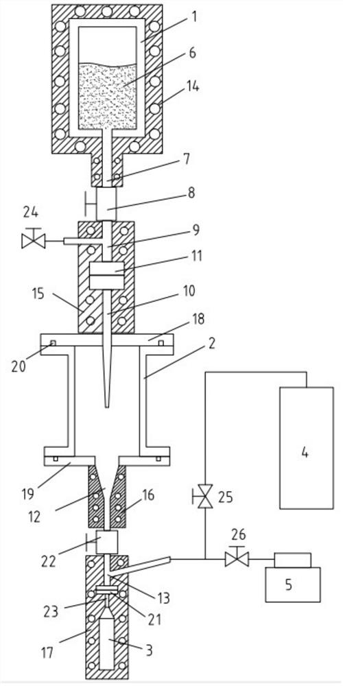
[0034] Such as figure 1 As shown, the present invention provides a high-temperature heat pipe working medium filling device, which includes a working medium container 1, a first pipeline 7, a first valve 8, a second pipeline 9, a first joint 11, Conical pipe 10 , quartz container, funnel 12 , second valve 22 , tee pipe 13 , second joint 21 , packaging pipe 23 and high temperature heat pipe 3 . Wherein, the quartz container includes a quartz tube 2, a first flange 18 and a second flange 19, the top and bottom of the quartz tube 2 are respectively connected with the first flange 18 and the second flange 19 through a sealing groove 20, and the working fluid container 1 A high-purity working medium 6 is set in the medium, and a high vacuum is kept in the working medium container 1, that is, 10 -3 ~10 - 5Pa. The first end of the tapered tube 10 is connected to the first joint 11, the second end passes through the first flange 18 and extends into the lumen of the quartz tube 2, ...


PUM


Abstract

The invention discloses a high-temperature heat pipe working medium filling device and method. The device comprises a working medium container, a conical pipe, a quartz container, a packaging pipe anda high-temperature heat pipe which are arranged sequentially from top to bottom, the bottom of the working medium container is in communication with the first end of a first communicating pipeline, the second end of the first communicating pipeline is connected with the first end of the conical pipe, the second end of the conical pipe is arranged in a cavity of the quartz container, the bottom ofthe quartz container is in communication with the first end of a second connecting pipeline, the second end of a second communicating pipeline is in communication with the packaging pipe, the packaging pipe is communicated with the high-temperature heat pipe, the first end of the first communicating pipeline is connected with the second end of the first communicating pipeline through a first valve, and the first end of the second communicating pipeline is connected with the second end of the second communicating pipeline through a second valve. According to the device and method, human contact is avoided, and the risk that the working medium is polluted in the filling process is reduced; the device can realize continuous filling and is suitable for continuous production; and the device issimple in structure and convenient to operate.

Description

technical field [0001] The invention belongs to the technical field of heat pipes, and in particular relates to a high-temperature heat pipe working fluid charging device and method. Background technique [0002] The heat pipe is a high-performance heat transfer element. Its structure is relatively simple. The shell is made of a metal tube, and its inner wall is attached with a capillary core to use capillary force to make the working fluid move within the capillary core without being restricted by the position of the heat pipe. The tube shell is sealed after being vacuumed, and an appropriate working medium is poured in. During operation, the working medium in the evaporating section is heated, and the working medium evaporates into steam, which flows through the adiabatic section to the condensing section. In the condensation section, the steam is cooled, condenses into a liquid, releases heat, and transfers it to objects outside the tube. The liquid working medium in the...

Claims


Application Information

Patent Timeline
Patent Type & Authority Patents(China)
IPC IPC(8): F28D15/02
CPCF28D15/0283
Inventor 张平白玉潭马伟史波杨道国徐德好
Owner GUILIN UNIV OF ELECTRONIC TECH
Learn More