Camera signal calibration system

A technology for calibrating systems and cameras, applied in the circuit field, can solve problems such as analog signal distortion, unaccounted for changes in signal noise, and increase in signal noise, and achieve the effects of preventing signal distortion, reducing signal-to-noise ratio, and improving accuracy

Active Publication Date: 2019-11-05
深圳市众安威视技术有限公司
View PDF6 Cites 9 Cited by
  • Summary
  • Abstract
  • Description
  • Claims
  • Application Information

AI Technical Summary

Problems solved by technology

[0003] Compared with the prior art, the output data with the ID number and the serial time signal output by the main camera and the slave camera are transmitted to the signal multiplexing processor, and the signal multiplexing processor recognizes the ID number, the serial time signal , to obtain the data corresponding to the main camera and the slave camera and the exposure process. The process of multipl

Method used


Image

  • Camera signal calibration system
  • Camera signal calibration system
  • Camera signal calibration system

Examples


Embodiment Construction

[0013] Regarding the aforementioned and other technical contents, features and effects of the present invention, refer to the appended figure 1 to attach image 3 It will be apparent from the detailed description of the embodiments. The structural contents mentioned in the following embodiments are all based on the accompanying drawings of the description.

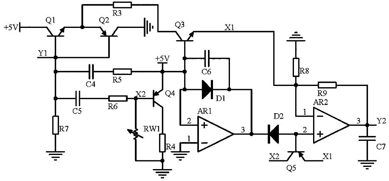
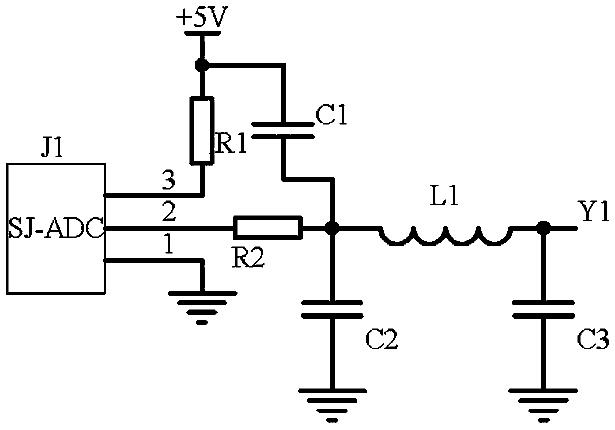
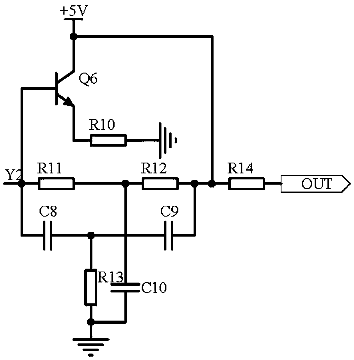
[0014] A camera signal calibration system, comprising a frequency acquisition circuit, a separation feedback circuit and a wave limiting output circuit, the frequency acquisition circuit acquires the modulated analog signal frequency in the controller, and the separation feedback circuit uses a triode Q4, a variable resistor RW1 Combined with capacitor C4 and capacitor C5, a synchronous separation circuit is formed to divide the signal into two signals of the same frequency and different amplitudes, and one channel is input into the noise reduction circuit composed of operational amplifier AR1, diode D1, and diode D2 to r...


PUM


Abstract

The invention discloses a camera signal calibration system. The camera signal calibration system comprises a frequency acquisition circuit, a separation feedback circuit and a wave-limiting output circuit. The frequency acquisition circuit acquires the modulated analog signal frequency in the controller; according to the separation feedback circuit, a triode Q4, a variable resistor RW1, a capacitor C4 and a capacitor C5 form a synchronous separation circuit to divide a signal into two paths of signals with the same frequency and different amplitudes, one path of the signal is input into a noise reduction circuit consisting of an operational amplifier AR1, a diode D1 and a diode D2 to reduce the signal-to-noise ratio, and in the second path, a triode Q1 and a triode Q2 form a push-pull circuit to prevent signal crossover distortion; a triode Q3 is used for detecting the potential difference of the two paths of signals; finally, an operational amplifier AR2, a resistor R8 and a resistorR9 form a differential circuit to carry out differential processing on the signal; the wave-limiting output circuit uses resistors R11-R13 and a triode Q6 to form a wave-limiting circuit to limit a signal waveform and then inputs the signal waveform into a modulated analog signal in the controller, and the output signal is a compensation signal after the controller received the modulated analog signal.

Description

technical field [0001] The invention relates to the field of circuit technology, in particular to a camera signal calibration system. Background technique [0002] In the prior art, a dual camera signal processing method and system (application number: 201711407334.0), the disclosed processing method includes: step 1, synchronous exposure of the master camera and the slave camera; step 2, the output of the master camera and the slave camera The output data with ID number and serial time signal is transmitted to the signal multiplexing processor, and the signal multiplexing processor obtains the data corresponding to the master camera and the slave camera and the exposure process by identifying the ID number and the serial time signal, and sends the master The camera and the output data from the camera are multiplexed and then transmitted to the back-end processor for multiplexing; step 3, the back-end processor receives the multiplexed output data and performs image processi...

Claims


Application Information

Patent Timeline
IPC IPC(8): H04N5/232H04N5/217
CPCH04N23/81H04N23/60
Inventor 刘国强刘伊杰钟雪梅余银程玉添谢银玉许世荣林金飞周日师
Owner 深圳市众安威视技术有限公司
Why Eureka
Try Eureka