
A semiconductor electroplating machine

An electroplating machine and semiconductor technology, applied in semiconductor devices, circuits, electrolytic components, etc., can solve the problems of easy leakage of odors and affect the health of workers, and achieve the effect of improving the rate of waste gas treatment

Active Publication Date: 2021-07-16
江苏晶度半导体科技有限公司
View PDF8 Cites 0 Cited by
  • Summary
  • Abstract
  • Description
  • Claims
  • Application Information

AI Technical Summary

Problems solved by technology

[0003] The purpose of the present invention is to provide a semiconductor electroplating machine to solve the problem that the general electroplating machine proposed in the above-mentioned background technology is not equipped with a waste gas treatment device. When performing electroplating work, the pungent smell is easy to leak, which will affect the health of the staff. health problems

Method used


Image

  • A semiconductor electroplating machine
  • A semiconductor electroplating machine
  • A semiconductor electroplating machine

Examples


Embodiment 1

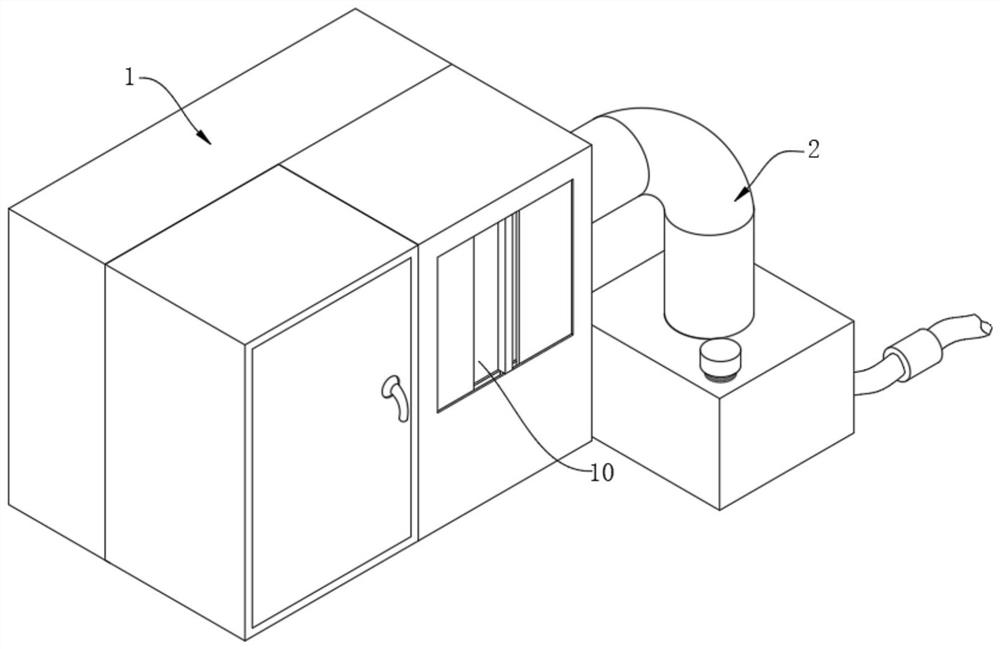
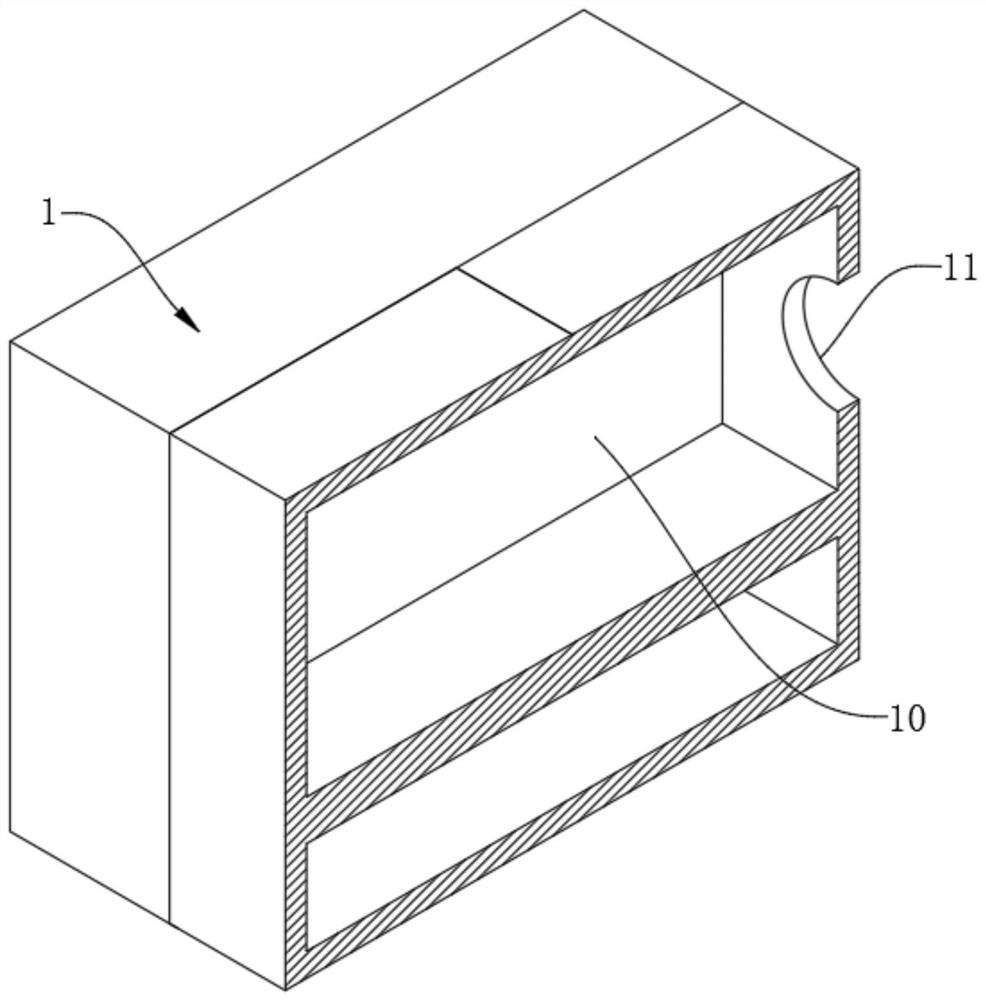
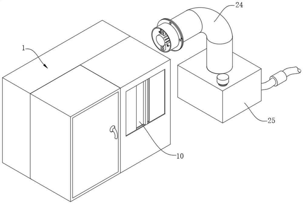
[0029] A semiconductor electroplating machine, such as Figure 1 to Figure 5 As shown, including the device main body 1, the interior of the device main body 1 is provided with a cavity 10, and a through hole 11 communicating with the outside is provided on one side wall of the cavity 10; the device main body 1 is also provided with a waste gas treatment device 2 The exhaust gas treatment device 2 includes a sleeve 20 tightly welded on the wall of the through hole 11. The sleeve 20 is a hollow columnar structure. The cover 27 is internally provided with an annular groove communicating with the outside world, and one end is a closed cylindrical structure. The driving motor 21 is located in the annular groove inside the protective cover 27, and the size of the driving motor 21 is the same as that of the annular groove inside the protective cover 27. The dimensions are matched to ensure that the driving motor 21 can be stably placed in the annular groove inside the protective cov...

Embodiment 2

[0041] In the specific operation, in order to ensure that the exhaust gas enters the exhaust pipe 24 more smoothly, the device main body 1 is improved on the basis of Embodiment 1. As a preferred embodiment, such as Figure 6 As shown, one side of the main body 1 of the device is tightly welded with a fixed plate 3 arranged horizontally, the fixed plate 3 is provided with a fan 30, the fan 30 is provided with a fixed base, and the fixed base is provided with several The threaded hole through the threaded hole, the threaded hole in the fixed base facing the fan 30 in the fixed plate 3 is also provided with a threaded hole connected with the outside world, and then the fixed base on the fan 30 is fixed and installed on the fixed base with fastening bolts. It can be installed on board 3, which is convenient for installation;

[0042] The air outlet pipe on the fan 30 is connected with the cavity 10, and the cavity wall of the cavity 10 is provided with a through hole for the air ...


PUM


Abstract

The invention relates to the technical field of electroplating equipment, in particular to a semiconductor electroplating machine, which includes a device main body, and a cavity is provided inside the device main body; a waste gas treatment device is also provided on the device main body, and the waste gas treatment device includes a The sleeve on the sleeve, the drive motor is installed inside the sleeve, several circular fan blades arranged at equal intervals are tightly welded on the transmission shaft, the sleeve is equipped with an exhaust pipe, and the end pipe body of the exhaust pipe is provided with In the exhaust gas treatment box, a fixed plate arranged horizontally is tightly welded on one side of the main body of the device, and a fan is arranged on the fixed plate. The invention is simple in operation and convenient in use, realizes the treatment of waste gas generated in the electroplating process, and reduces the adverse effects of waste gas on human body.

Description

technical field [0001] The invention relates to the technical field of electroplating equipment, in particular to a semiconductor electroplating machine. Background technique [0002] Electroplating is the process of plating a thin layer of other metals or alloys on some metal surfaces by using the principle of electrolysis. At present, there are many types of electroplating machines on the market. When producing semiconductors, electroplating machines are also needed. There is no waste gas treatment device on the electroplating machine. During the electroplating work, the pungent smell is easy to leak out, which affects the health of the staff. In view of this, we propose a semiconductor electroplating machine. Contents of the invention [0003] The purpose of the present invention is to provide a semiconductor electroplating machine to solve the problem that the general electroplating machine proposed in the above-mentioned background technology is not equipped with a w...

Claims


Application Information

Patent Timeline
Patent Type & Authority Patents(China)
IPC IPC(8): C25D7/12C25D17/00C25D21/04
CPCC25D7/12C25D17/00C25D21/04
Inventor 孙国标杜良辉张勇
Owner 江苏晶度半导体科技有限公司
Learn More