Wireless ultrasonic detection device

An ultrasonic testing and wireless technology, which is applied in the direction of using sound wave/ultrasonic wave/infrasonic wave to analyze solids and optical testing for flaws/defects, etc. It can solve problems that affect the efficiency and progress of inspection work, and achieve convenient review work, reduced labor, and convenient detection. Effect

Pending Publication Date: 2019-11-08
曼图电子(上海)有限公司
View PDF0 Cites 0 Cited by
  • Summary
  • Abstract
  • Description
  • Claims
  • Application Information

AI Technical Summary

Problems solved by technology

However, the current automatic ultrasonic testing requires a large number of probes, so the number of probe lines is often relatively large. In addition to the mechanical control cables, there are many cables that need to be connected on site. Due to the influence of the working environment and space, generally The control operation platform is far away from the actual operation area, so the cable length is relatively long, which requires reasonable planning and arrangement. If the on-site operation environment is harsh and the space is narrow, the requirements for the skills and experience of the operators are very high, and the operators need to be constantly Monitoring and tracking at the job site to prevent wire winding, wire pulling, wire jamming, etc. that affect the inspection, and once this happens, not only the inspection is interrupted, the wire needs to be changed again, but also the flat cable must be re-routed, which greatly affects the inspection. In order to check the efficiency and progress of the work

Method used


Image

  • Wireless ultrasonic detection device

Examples


Embodiment Construction

[0016] The specific implementation manners of the present invention will be further described below in conjunction with the drawings and examples. The following examples are only used to illustrate the technical solution of the present invention more clearly, but not to limit the protection scope of the present invention.

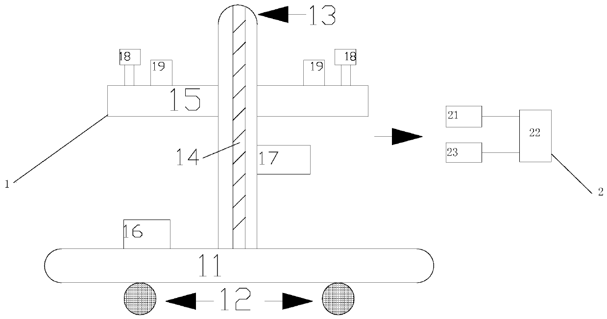
[0017] Such as figure 1 As shown, the present invention is a wireless ultrasonic detection device, including an operating system terminal 1 and a control terminal 2, the operating system terminal 1 and the control terminal 2 are connected, and the operating system terminal 1 includes a circumferential scanning shaft 11, a magnetic wheel 12, a shaft To scan axis 13, screw mandrel 14, frock 15, first miniature camera 16, second miniature camera 17 and ultrasonic probe 18, be provided with magnetic wheel 12 under circumferential scanning axis 11, circumferential scanning axis 11 and shaft Connect to the scanning shaft 13, the axial scanning shaft 13 is provid...


PUM


Abstract

The invention discloses a wireless ultrasonic detection device. The device comprises an operating system end and a control end, and the operating system end is connected with the control end. The operating system end comprises a circumferential scanning shaft, a magnetic wheel, an axial scanning shaft, a screw rod, a tool, a first micro camera, a second micro camera and an ultrasonic probe, wherein the magnetic wheel is arranged on the lower portion of the circumferential scanning shaft, the circumferential scanning shaft is connected with the axial scanning shaft, a lead screw is arranged inthe axial scanning shaft, the axial scanning shaft is connected with the tool, the first micro camera is arranged on the circumferential scanning shaft, the second micro camera is arranged on the axial scanning shaft, and the ultrasonic probe is arranged on the tool. The control end comprises a phased array ultrasonic instrument, a computer and a mechanical control system, the phased array ultrasonic instrument is connected with the computer, and the mechanical control system is connected with the computer. The wireless ultrasonic detection device which is convenient to detect and reduces labor is manufactured by adopting the technical scheme. A control operation platform can be arranged at the position away from the operation area, so that the harm of the severe environment to the human body is reduced.

Description

technical field [0001] The invention relates to the field of automatic ultrasonic detection, in particular to a wireless ultrasonic detection device. Background technique [0002] In the nuclear industry and other industries, the proportion of in-service welds or base metal inspections is quite high, and ultrasound is a common method for weld and base metal inspections. The demand for automatic ultrasonic testing applications is becoming more and more intense. However, the current automatic ultrasonic testing requires a large number of probes, so the number of probe lines is often relatively large. In addition to the mechanical control cables, there are many cables that need to be connected on site. Due to the influence of the working environment and space, generally The control operation platform is far away from the actual operation area, so the cable length is relatively long, which requires reasonable planning and arrangement. If the on-site operation environment is hars...

Claims


Application Information

Patent Timeline
Patent Type & Authority Applications(China)
IPC IPC(8): G01N29/04G01N21/88
CPCG01N21/88G01N29/04
Inventor 龙绍军
Owner 曼图电子(上海)有限公司
Why Eureka
Try Eureka