
Testing device for friction power generator

A friction generator and testing device technology, which is applied in the direction of motor generator testing, measuring devices, measuring device casings, etc., can solve the problems of poor accuracy of testing devices, achieve easy mobile use, small footprint, and improve testing accuracy degree of effect

Pending Publication Date: 2019-11-08
LANZHOU INST OF CHEM PHYSICS CHINESE ACAD OF SCI +1
View PDF0 Cites 0 Cited by
  • Summary
  • Abstract
  • Description
  • Claims
  • Application Information

AI Technical Summary

Problems solved by technology

[0003] The purpose of the present invention is to provide a friction generator test device, which solves the problem of poor accuracy of the test device

Method used


Image

  • Testing device for friction power generator
  • Testing device for friction power generator
  • Testing device for friction power generator

Examples


Embodiment 1

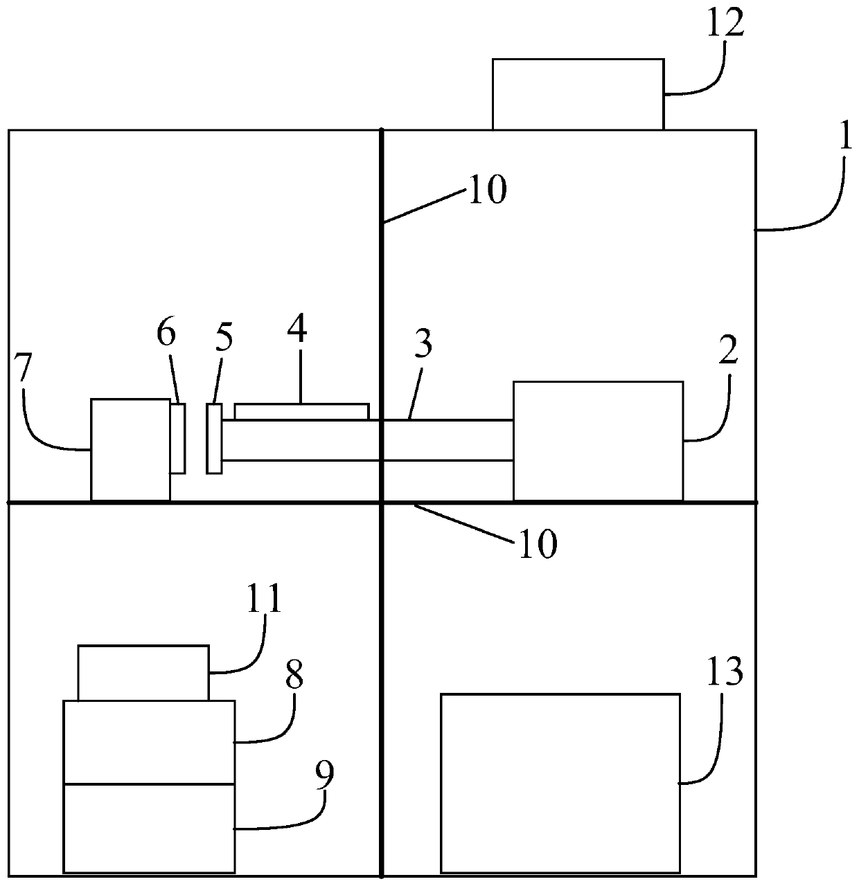
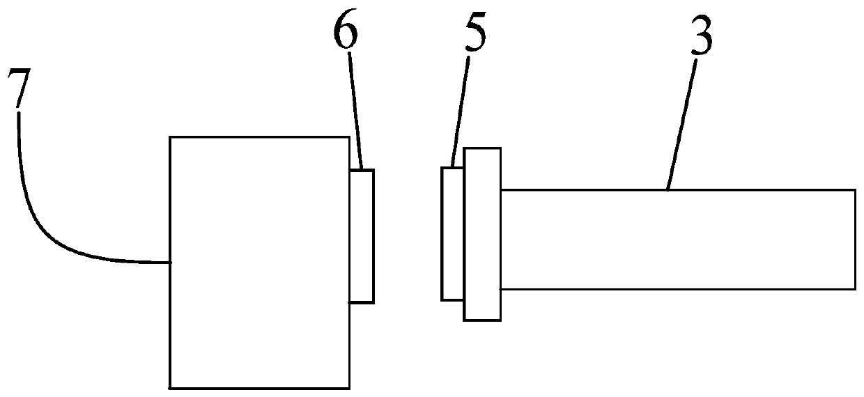
[0050] The present embodiment 1 provides a friction generator testing device, figure 1 It is a structural diagram of the friction generator testing device provided by Embodiment 1 of the present invention. see figure 1 , the friction generator testing device includes: a shielding box 1, a linear motor 2, a motor push rod 3, a solid-liquid vibration fixed table 4, a magnetic sample plate, a friction generator to be tested, a flat pressure sensor 7, an ammeter 8 and Voltmeter9. The friction generator to be tested in this embodiment 1 is a solid-liquid friction generator or a solid-solid friction generator.

[0051] The interior of the shielding box is divided into four spaces with a partition 10, specifically the inside of the shielding box is divided into a first space and a second space with a first partition, and the first space is divided into a third space and a second space with a second partition. Four spaces, the second space is divided into the fifth space and the si...

Embodiment 2

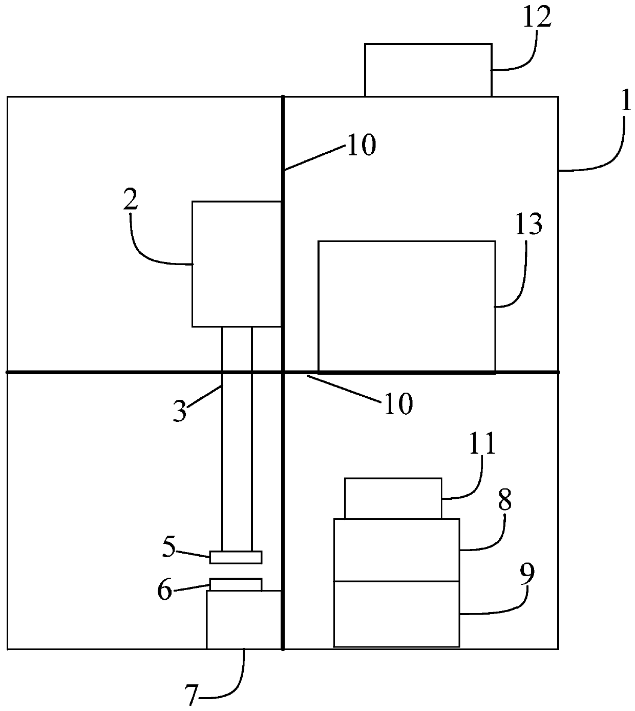
[0084] This embodiment 2 provides a friction generator testing device, image 3 It is a structural diagram of the friction generator testing device provided by Embodiment 2 of the present invention. see image 3 , the friction generator testing device includes: a shielding box 1, a linear motor 2, a motor push rod 3, a magnetic sample plate, a friction generator to be tested, a flat pressure sensor 7, an ammeter 8 and a voltmeter 9. The friction generator to be tested in Example 2 is a solid-solid friction generator.

[0085] The inside of the shielding box is divided into the first space and the second space by the first partition, the first space is divided into the third space and the fourth space by the second partition, and the second space is divided into the fifth space by the third partition and the sixth space. The shielding box is a Faraday shielding box. The material of the shielding box of present embodiment 2 can be good conductors such as copper, aluminum and...


PUM


Abstract

The invention discloses a testing device for a friction power generator and relates to the technical field of power generators. The testing device for the friction power generator comprises a shielding box, a linear motor, a motor push rod, a solid-liquid vibration fixing table, a magnetic-attraction-type sample plate, a to-be-tested friction power generator, a slab pressure sensor, a current meter and a voltage meter; through linear reciprocation movement of the linear motor, the application force generated by the to-be-tested friction power generator can be precisely controlled; the slab pressure sensor can further measure the collision intensity of the linear motor to the to-be-tested friction power generator in real time, and the precision of testing the to-be-tested friction power generator is improved. The shielding box of the testing device for the friction power generator is an integrated shielding box and is small in floor area and more convenient to move and use; the to-be-tested friction power generator can be detected in the vertical and horizontal directions, and the testing device is suitable for the to-be-tested friction power generator which needs to eliminate a gravity factor.

Description

technical field [0001] The invention relates to the technical field of generators, in particular to a friction generator testing device. Background technique [0002] The friction generator is a new research direction that has emerged in recent years. Since its invention in 2012, it has attracted more and more attention. The friction generator can collect the static electricity generated by the contact or friction of two objects into usable electrical energy. Frictional nanogenerators are mainly divided into sliding type and contact type according to the driving mode. The principle of the contact triboelectric generator is that the periodic contact-separation of two polymer films will have opposite triboelectric charges, and the inner surfaces of the two polymer films will be in close contact and charge transfer will occur, thus making a polymerization The inner surface of the polymer is positively charged, and the inner surface of the other polymer is negatively charged; ...

Claims


Application Information

Patent Timeline
Patent Type & Authority Applications(China)
IPC IPC(8): G01R31/34G01R1/02G01R1/04G01R1/18
CPCG01R31/34G01R1/02G01R1/04G01R1/18
Inventor 王道爱冯雁歌周峰刘维民
Owner LANZHOU INST OF CHEM PHYSICS CHINESE ACAD OF SCI
Learn More