Micro driver based on surface plasmon polariton waveguide structure

A surface plasmon and waveguide structure technology, applied in the direction of microstructure devices composed of deformable elements, microstructure technology, microstructure devices, etc., can solve the problems of lack of independence, high temperature rise of the driving arm, and difficult overall structure Miniaturization and other issues to achieve the effect of multiple control, high energy density, good controllability

Inactive Publication Date: 2019-11-08
NANJING UNIV OF POSTS & TELECOMM
View PDF4 Cites 2 Cited by
  • Summary
  • Abstract
  • Description
  • Claims
  • Application Information

AI Technical Summary

Problems solved by technology

These driving mechanisms are mostly controlled by electrical signals. Although the main body size can be made very small, most of them need to be connected to the external control system through wires, or need a built-in battery as a power source. The overall structure is difficult to miniaturize and lacks independence. , restricting their scope of application
[0003] Existing photothermal drive technologies mostly rely on the spot formed by the laser beam itself on the expansion arm as a heat source, and the entire expansion arm is heated unevenly, which limits the efficiency of photothermal drive; Multiple laser beams are required, which increases the complexity of the control system and is not conducive to the miniaturization of the entire system; in addition, in order to obtain a larger photothermal deflection driving amount, it is necessary to increase the laser power, which can easily lead to local temperature rise of the driving arm Excessively high, causing failure and damage to the micro-driver
These problems have restricted the further development of photothermal drive to a certain extent.

Method used


Image

  • Micro driver based on surface plasmon polariton waveguide structure
  • Micro driver based on surface plasmon polariton waveguide structure
  • Micro driver based on surface plasmon polariton waveguide structure

Examples


Embodiment 1

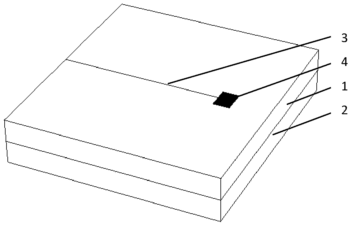
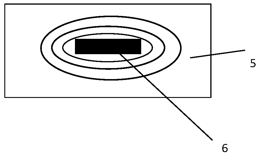
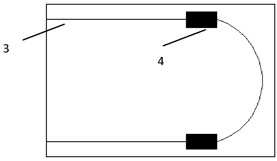
[0036] This embodiment provides a curved micro-actuator based on a surface plasmon waveguide structure, the structure of which is as follows Image 6 and Figure 7 As shown, it includes a two-layer laminated surface plasmon waveguide layer 1 and a driving arm layer 2 . A surface plasmon waveguide structure 3 and a light-to-heat conversion region 4 are arranged on the surface plasmon waveguide layer 1. By introducing optical signals, electrical signals or photoelectric multiplexing signals into the surface plasmon waveguide structure 3 for transmission, the transmission mode of the incident signal is limited by the surface plasmon waveguide structure 3, so that the input photoelectric signal is transmitted to the photothermal The conversion region 4 generates a thermal effect to realize the action of the driving arm layer 2 .

[0037]The surface plasmon waveguide layer 1 can be a single layer or multiple layers, and the light-to-heat conversion region 4 can be located in the ...

Embodiment 2

[0040] This embodiment provides an "S" curved micro-actuator based on a surface plasmon waveguide structure, the structure of which is as follows Figure 8 As shown, it includes two surface plasmon waveguide layers 1 stacked in sequence, a top waveguide layer 11 and a bottom waveguide layer 12 . Wherein the top waveguide layer 11 and the bottom waveguide layer 12 are provided with a surface plasmon waveguide structure 3 , a top layer light-to-heat conversion region 41 and a bottom layer light-to-heat conversion region 42 . By introducing optical signals, electrical signals or photoelectric multiplexing signals into the surface plasmon waveguide structure 3 for transmission, the transmission mode of the incident signal is limited by the surface plasmon waveguide structure 3, so that the input photoelectric signal is transmitted to the top layer of light The heat conversion region 41 and the bottom light-to-heat conversion region 42 generate a thermal effect to realize the actio...

Embodiment 3

[0044] This embodiment provides a continuously curved surface plasmon waveguide structure micro-driver, the structure of which is as follows Figure 9 As shown, it includes a top waveguide layer 11 , a driving arm layer 2 and a bottom waveguide layer 12 stacked in sequence. Wherein the top waveguide layer 11 and the bottom waveguide layer 12 are respectively provided with a surface plasmon waveguide structure 3 and a top light-to-heat conversion region 41 and a bottom light-to-heat conversion region 42 .

[0045] By introducing optical signals, electrical signals or photoelectric multiplexing signals into the surface plasmon waveguide structure 3 for transmission, the transmission mode of the incident signal is limited by the surface plasmon waveguide structure 3, so that the input photoelectric signal is transmitted to the top layer of light The heat conversion region 41 and the bottom light-to-heat conversion region 42 generate a thermal effect to realize the action of the m...


PUM

PropertyMeasurementUnit
thicknessaaaaaaaaaa
thicknessaaaaaaaaaa

Abstract

The invention relates to a micro driver based on a surface plasmon polariton waveguide structure. The micro driver structurally comprises two parts, namely a surface plasmon polariton waveguide layerand a driving arm layer. The surface plasmon polariton waveguide layer contains a surface plasmon polariton waveguide structure and a photo-thermal conversion region, and two or more layers of the surface plasmon polariton waveguide layer and the driving arm layer are combined in a laminated manner. According to the micro driver based on the surface plasmon polariton waveguide structure, the surface plasmon polariton waveguide structure is used for controlling the transmission mode of the incident photoelectric signal, accurate control over the photoelectric signal can be realized through thedesign of the surface plasmon polariton waveguide structure, the energy size and mode distribution or field distribution of the optical signal transmitted to the photo-thermal conversion area can be accurately controlled, and accurate control of different actions of the driving arm is realized.

Description

technical field [0001] The invention relates to a micro-driver, in particular to a micro-driver based on a surface plasmon waveguide structure. Background technique [0002] With the continuous exploration and research of human beings into the micro world, Micro optical electromechanical system (MOEMS), as an important branch field of micro and nano technology, has attracted the attention and attention of researchers all over the world. In micro actuators, micro sensors , micro power system and other fields have been widely used. Among them, the micro-driver, as an important actuator and power source of the micro-opto-electromechanical system, is one of the key technologies in this field. In recent years, micro-drives including micro-motors, micro-valves, micro-gears, micro-pumps, and micro-mechanical switches have been continuously realized, so that sensors, drives, and calculators of conventional size can be integrated in centimeter- and millimeter-scale systems. , makin...

Claims


Application Information

Patent Timeline
Patent Type & Authority Applications(China)
IPC IPC(8): G02F1/01B81B3/00
CPCG02F1/0147G02F1/011B81B3/0029
Inventor 李若舟严静于映方玉明
Owner NANJING UNIV OF POSTS & TELECOMM
Why Eureka
Try Eureka