
Single-input port SIW feeding structure and antenna array

A technology of antenna array and input port, which is applied in the direction of antenna array, specific array feeding system, antenna, etc., can solve the problems of radiation leakage, difficult layout, and reduced antenna radiation efficiency, so as to simplify design and processing and ensure performance Effect

Active Publication Date: 2019-11-08
南通大学技术转移中心有限公司
View PDF6 Cites 4 Cited by
  • Summary
  • Abstract
  • Description
  • Claims
  • Application Information

AI Technical Summary

Problems solved by technology

In existing reports, differential antennas are often fed by probes, microstrip lines, etc., but the exposed structure in this type of feeding method is likely to cause radiation leakage and reduce the radiation efficiency of the antenna.
Moreover, this type of feeding method is often difficult to layout due to the use of large-volume differential power distribution networks in antenna array design.

Method used


Image

  • Single-input port SIW feeding structure and antenna array
  • Single-input port SIW feeding structure and antenna array
  • Single-input port SIW feeding structure and antenna array

Examples


Embodiment Construction

[0034] In order to facilitate the understanding of the present invention, the present invention will be described more fully below with reference to the associated drawings. Typical embodiments of the invention are shown in the drawings. However, the present invention can be embodied in many different forms and is not limited to the embodiments described herein. Rather, these embodiments are provided so that the disclosure of the present invention will be thorough and complete. It should be understood that the embodiments of the present invention and the specific features in the embodiments are detailed descriptions of the technical solutions of the present application, rather than limitations on the technical solutions of the present application. In the case of no conflict, the embodiments of the present invention and the technical features in the embodiments can be combined with each other.

[0035]It should be noted that when an element is referred to as being “fixed” to ...


PUM


Abstract

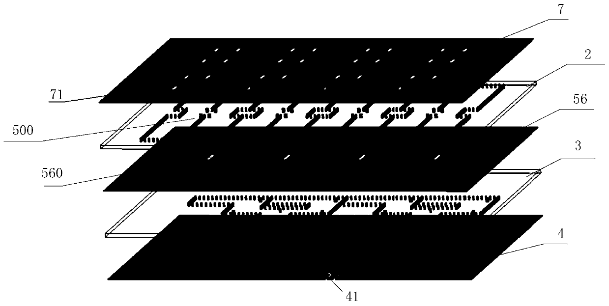
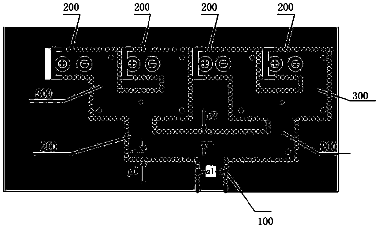
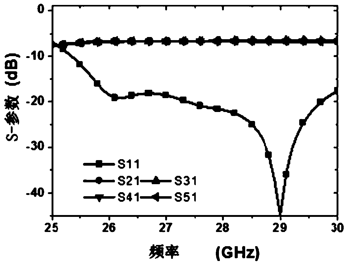
The invention discloses a single-input port SIW feeding structure and an antenna array. The feeding structure comprises a TE10 mode SIW and a TE20 mode SIW, wherein the TE10 mode SIW comprises N levels of power dividing arms facing a first direction; the TE20 mode SIW comprises 2<N> TE20 mode SIW cavities; 2<N> first coupling gap couplings are formed between the TE10 mode SIW and the TE20 mode SIW; corresponding 2<N> groups of second coupling gaps are formed at the top parts of the 2<N> TE20 mode SIW cavities, and each group is formed by M pairs of second coupling gaps; the rear ends of 2<N> final-level power dividing arms are bent to a second direction, the 2<N> first coupling gaps are corresponding to 2<N> final-level power dividing arms and are also corresponding to the 2<N> TE20 mode SIW cavities; a horizontal distance of a half waveguide wavelength exists between the first coupling gap and the end part of the rear bending part of the corresponding final-level power dividing arm toprovide 2<N> paths of reverse phase signals; each path of reverse phase signals is fed to the corresponding TE20 mode SIW cavity and is then outputted through the corresponding M pairs of second coupling gaps, and a radiation unit array is excited to from an antenna array.

Description

technical field [0001] The invention relates to the communication field, in particular to an SIW feeding structure with a single input port and an antenna array. Background technique [0002] With the development of the millimeter-wave frequency band, research on high-performance millimeter-wave antenna arrays has received extensive attention. Differentially fed antennas have obvious advantages in suppressing spurious modes, reducing cross-polarization, and improving pattern symmetry performance. In existing reports, differential antennas are often fed by probes, microstrip lines, etc., but the exposed structure in this type of feeding method is likely to cause radiation leakage and reduce the radiation efficiency of the antenna. Moreover, this type of feeding method often brings layout difficulties due to the use of a large-volume differential power distribution network in antenna array design. The low-loss waveguide structure is more popular in the feed network of the mi...

Claims


Application Information

Patent Timeline
Patent Type & Authority Applications(China)
IPC IPC(8): H01Q1/50H01Q21/00H01Q1/48
CPCH01Q1/48H01Q1/50H01Q21/0006
Inventor 唐慧陈建新葛杰褚慧
Owner 南通大学技术转移中心有限公司
Learn More