Electric coagulation and electric cutting pliers

A technology of electrocution and electrocoagulation, which is applied in the field of medical devices, can solve the problems of poor surgical operation accuracy and precise electrocution of difficult target tissues, and achieve good applicability, reduce the number of parts, and improve accuracy

Pending Publication Date: 2019-11-12
CHENGDU MECHAN ELECTRONICS TECH
View PDF0 Cites 0 Cited by
  • Summary
  • Abstract
  • Description
  • Claims
  • Application Information

AI Technical Summary

Problems solved by technology

[0005] In view of this, the present application provides an electrocoagulation cutting forceps. By changing the electrode structure of the electrocoagulation forceps, the first electrode is embedded in the through groove of the second electrode, and the distal ends of the two electrodes are flush and insulated. When the tissue is in contact, the tissue conducts the two electrodes to form a loop, and the current burns the passing tissue, causing the tissue to lose water and denature. The effect of palpable hemostasis solves the problem that the accuracy of electrocoagulation electric cutting forceps is poor, and it is difficult to conveniently perform precise electrocution and electrocoagulation on small area target tissues

Method used


Image

  • Electric coagulation and electric cutting pliers
  • Electric coagulation and electric cutting pliers
  • Electric coagulation and electric cutting pliers

Examples


Embodiment 1

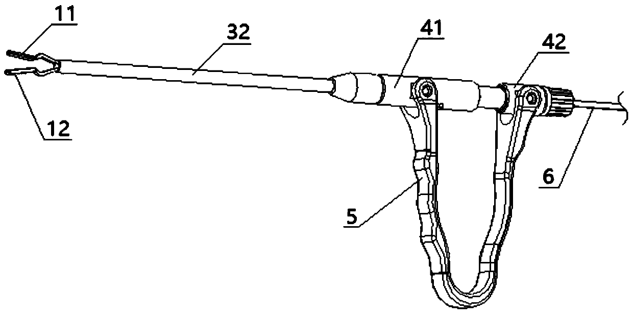
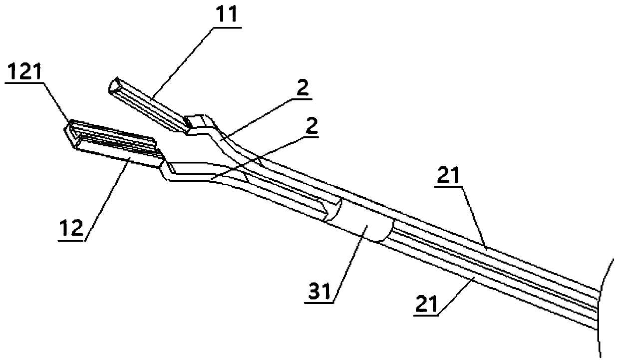
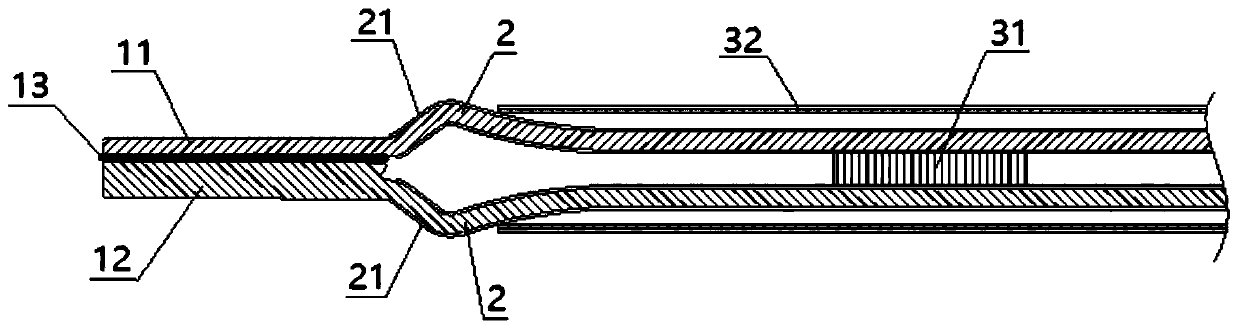
[0044] Please refer to Figure 1-4 , This embodiment provides an electrocoagulation cutting pliers, including a first electrode 11 and a second electrode 12 arranged in pairs, at least one of the first electrode 11 and the second electrode 12 is at a separate position and relative to the other. Move between the approaching positions; when the first electrode 11 and the second electrode 12 are in the approaching position, the distal ends of the first electrode 11 and the second electrode 12 are aligned planes perpendicular to the extending direction of the distal ends. A first electrical insulation layer 13 is provided between the first electrode 11 and the second electrode 12, and the first electrical insulation layer 13 is an elastic electrical insulation layer. The opposite sides of the first electrode 11 and the second electrode 12 are respective clamping parts, and the contact area between the clamping part of the first electrode 11 and the tissue is smaller than the contact...

Embodiment 2

[0052] The difference between this embodiment and the first embodiment is that a gap is left between the first electrode 11 and the second electrode 12. By leaving a gap between the first electrode 11 and the second electrode 12, the two electrodes cannot be contacted and conducted. The size of the gap can be adjusted according to the voltage, thereby optimizing the structure of the operating terminal electrode, and improving the accuracy and effect of point touch hemostasis.

Embodiment 3

[0054] In the present application, the distal ends of the first electrode 11 and the second electrode 12 are flush, which means that the connection between the ends of the first electrode 11 and the second electrode 12 is closest to the first electrode 11 and the second electrode. The extension direction of 12 is vertical.

[0055] Please refer to Figure 5 In this embodiment, a structure in which the ends of the first electrode 11 and the second electrode 12 are flush is provided. The end of the first electrode 11 is a bevel, the end of the second electrode 12 is a plane, and the first electrode 11 and the second electrode 12 are flat. The connection line at the closest position of the electrode 12 is still perpendicular to the extending direction of the electrode, that is, the first electrode 11 and the second electrode 12 are flush.

[0056] Please refer to Image 6 with Figure 7 In other embodiments, the first electrode 11 and the second electrode 12 can also be arranged as s...


PUM


Abstract

The invention discloses electric coagulation and electric cutting pliers. The electric coagulation and electric cutting pliers comprise a handle assembly and an electrode assembly, wherein the electrode assembly can perform telescopic clamping motion under the control of the handle assembly, and comprises a first electrode and a second electrode which are mutually isolated; when the first electrode and the second electrode are under an approaching condition of the telescopic clamping motion, the first electrode is embedded in a through groove in the second electrode, and is level with the farend of the second electrode; the first electrode is embedded in the through groove in the second electrode, so that the far ends of the two electrodes are level and insulated; when the electrodes arein contact with tissue, the two electrodes are conducted by the tissue to form a loop, the electric current burns the passing tissue, so that the tissue is subjected to dehydration and modification; and tissue in small region can be clamped by the far ends, so that fine surgery operations are realized, and the effect of point contacting blooding stopping can also be realized, so that the problemsthat existing electric coagulation and electric cutting pliers are poor in surgery operation accuracy, and precise electric cutting and precise electric coagulation cannot be conveniently performed ontarget tissue in the small region are solved.

Description

Technical field [0001] The invention relates to the field of medical equipment, in particular to an electrocoagulation electric cutting forceps. Background technique [0002] With the development of medical technology, the application of minimally invasive visual surgery is gradually increasing in clinical surgery, especially abdominal surgery or gynecological surgery. At present, minimally invasive surgery usually requires a variety of instruments to be used together, such as hysterectomy, which requires electrocutting forceps, electrocoagulation forceps, electrosurgical forceps, and extraction forceps, which are used to cut, coagulate, stop bleeding, and remove tissues. operating. [0003] Due to the limited operating space in the abdominal cavity during surgery, it is difficult to accommodate multiple instruments at the same time. Therefore, the current surgical instruments are continuously improved in integration and multi-function. For example, a cutting knife is arranged si...

Claims


Application Information

Patent Timeline
Patent Type & Authority Applications(China)
IPC IPC(8): A61B18/14A61B18/12
CPCA61B18/12A61B18/1445A61B2018/00583A61B2018/00595A61B2018/00607A61B2018/1452
Inventor 贺强何朝东
Owner CHENGDU MECHAN ELECTRONICS TECH
Why Eureka
Try Eureka