Pipeline type micro-nano bubble generator

A nano-bubble and generating device technology, which is applied in transportation and packaging, gas/steam and liquid mixing, mixers, etc. It can solve the problems of unsatisfactory mixing effect of static mixer, inability to form gas residence area, poor bubble crushing effect, etc. , to achieve the effect of low price, convenient installation and disassembly, and convenient production

Pending Publication Date: 2019-11-12
SHANGHAI XINGHENG SCI & TECH
View PDF0 Cites 1 Cited by
  • Summary
  • Abstract
  • Description
  • Claims
  • Application Information

AI Technical Summary

Problems solved by technology

Static mixers are typical static gas-liquid mixing and bubble breaking structures, but for gas-liquid mixing and bubble breaking processes, due to the huge difference in gas-liquid viscosity, the mixing effect of static mixers is generally not ideal, even if it can To achieve better mixing effect, it also needs to consume very high pipeline pressure, and the economy is very poor
[0003] Venturi, ejector, etc. generate negative pressure locally to inhale gas, so that the structure that combines gas-liquid mixing, bubble breaking and air intake is t

Method used


Image

  • Pipeline type micro-nano bubble generator
  • Pipeline type micro-nano bubble generator

Examples


Embodiment 1

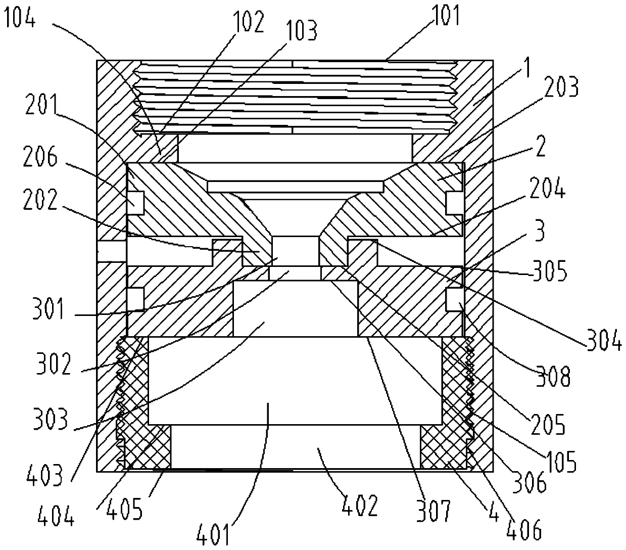
[0025] see figure 1 , a pipe-type micro-nano bubble generating device, comprising:

[0026] Cylindrical housing 1, water inlet pipe connection thread 101, and an annular protruding structure 104 facing the axial direction. The plane of the protruding structure facing the water inlet direction is called the first housing plane 102, and the plane facing the water outlet direction is called the housing second plane 103;

[0027] The first guide part 2, the first guide part is a two-section cylindrical structure, wherein the diameter of the cylindrical structure 201 close to the water inlet direction is larger than the diameter 202 of the cylindrical structure away from the water inlet direction, and in the axial direction There is an axisymmetric water channel on the top, and the diameter of the water channel is gradually reduced. Its function is to increase the water flow rate, reduce the hydrostatic pressure, and generate negative pressure; The plane is called the first plane...

Embodiment 2

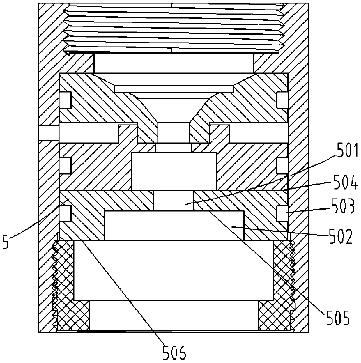
[0031] see figure 2 , in this embodiment, a third guide member 5 can be added between the second guide member 3 and the end cover member 4, which includes a first cavity 501, a second cavity 502, and an O-ring groove 503 ; The first plane 504, the second plane 505, and the third plane 506, the function of these accessories is to make the water channel smaller and then bigger, thereby improving the bubble breaking effect.

[0032] The invention effectively breaks large-sized air bubbles in the pipeline, and even breaks the air bubbles into micron levels, thereby greatly increasing the gas-liquid contact area; micron air bubbles with small diameters rise slowly in water, have large specific surface areas, and have negative charges on the surface , can comprehensively improve the cleaning ability of water for pesticide residues, oil stains, and detergent residues; at the same time, when cleaning with detergent, it can reduce the amount of detergent and improve the cleaning effec...


PUM


Abstract

The invention relates to a pipeline type micro-nano bubble generator. The pipeline type micro-nano bubble generator comprises a columnar shell, one end of the columnar shell is a water inlet end, andthe other end of the columnar shell is a water outlet end; a flow guiding component group is arranged in the columnar shell from the water inlet end to the water outlet end; and the flow guiding component group includes at least two flow guiding components, every flow guiding component has a hollow cavity, and the adjacent flow guiding components are attached to each other in order to make the internal diameters of the hollow cavities alternately contract and expand within the length range of the flow guiding component group. The pipeline type micro-nano bubble generator has the advantages ofgreat increase of the gas-liquid contact area, comprehensiveness in improvement of the ability of water to remove pesticide residues, oil stains and detergent residues, easiness in manufacturing, convenience in mounting and dismounting, and realization of free expansion of the quantity and the total length direction of the flow guiding components as needed.

Description

technical field [0001] The invention relates to a pipe-type micro-nano bubble generating device, which belongs to the technical field of micro-bubble generation. Background technique [0002] The existing bubble breaking device inside the pipeline includes a static mixing structure separated from the intake air and a structure combined with the intake air. Static mixers are typical static gas-liquid mixing and bubble crushing structures, but for the process of gas-liquid mixing and bubble crushing, due to the huge difference in gas-liquid viscosity, the mixing effect of static mixers is generally not ideal, even if it can To achieve a good mixing effect, it also needs to consume a very high pipeline pressure, and the economy is very poor. [0003] Venturi, ejector, etc. generate negative pressure locally to inhale gas, so that the structure that combines gas-liquid mixing, bubble breaking and air intake is the most commonly used gas-liquid mixing and bubble breaking structu...

Claims


Application Information

Patent Timeline
IPC IPC(8): B01F3/04B01F5/00
CPCB01F23/20B01F25/00
Inventor 王培
Owner SHANGHAI XINGHENG SCI & TECH
Why Eureka
Try Eureka