Catalyst continuous spray device used for fuel cell membrane electrode production

A fuel cell membrane and spraying device technology, which is applied to fuel cells, battery electrodes, spraying devices, etc., can solve the problems of easy adhesion of dust and impurities on the surface of the coating, continuous spraying work, and difficulty in large-scale production. Reduce manual intervention, ensure production consistency, and improve performance

Pending Publication Date: 2019-11-12
洺源科技(大连)有限公司
View PDF0 Cites 4 Cited by
  • Summary
  • Abstract
  • Description
  • Claims
  • Application Information

AI Technical Summary

Problems solved by technology

[0003] In the existing catalyst spraying equipment for the production of fuel cell membrane electrodes, a single nozzle is generally used, and an intermittent operation mode is adopted; After the completion, it is necessary to wait for a period of time before spraying the other side. The spraying work cannot be carried out continuously, and dust and impurities are easy to adhere to the surface of the coating; in the production process based on the existing production equipment, due to the need to reverse the film and other operations , can only be used in a single-piece manner, and most of the reversal, cutting, and fixing of the membrane require manual intervention, it is difficult to form large-scale production, the production cost is high, and the consistency is poor; therefore, there is an urgent need for a continuous catalyst for membrane electrode production. The spraying device realizes continuous spraying on both sides of the membrane at the same time, improves production efficiency and reduces production costs, and reduces manual interference in the process, ensuring the consistency of membrane electrode production

Method used


Image

  • Catalyst continuous spray device used for fuel cell membrane electrode production
  • Catalyst continuous spray device used for fuel cell membrane electrode production
  • Catalyst continuous spray device used for fuel cell membrane electrode production

Examples


Embodiment Construction

[0030] The preferred embodiments of the present invention will be described in detail below in conjunction with the accompanying drawings, so that the advantages and features of the present invention can be more easily understood by those skilled in the art, so as to define the protection scope of the present invention more clearly.

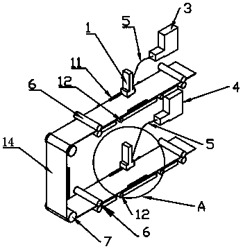
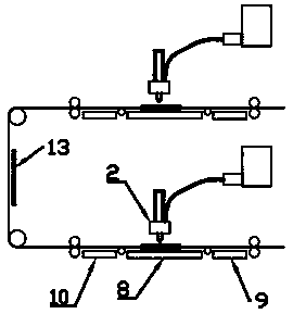
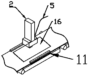
[0031] see figure 1 , figure 2 and image 3 , embodiments of the present invention include:

[0032] A catalyst continuous spraying device for fuel cell membrane electrode production, including: No. 1 spraying module, No. 2 spraying module, No. 1 feed pump 3, No. 2 feed pump 4, feed pipe 5, transfer roller 6, reverse Roller 7, spraying heating plate 8, pre-heating plate 9, rear heating plate 10, intermediate heating plate 13; No. 1 spraying module includes No. 1 spraying head 1, No. 1 feeding pump 3, feeding pipe 5, and conveying roller 6 , reversing roller 7; No. 2 spraying module includes No. 2 spraying head 2, No. 2 feeding pump 4, feeding...


PUM


Abstract

The invention discloses a catalyst continuous spray device used for fuel cell membrane electrode production. The catalyst continuous spray device comprises at least two spray modules, a heating moduleand at least bearing rollers. Each spray module comprises a spray nozzle, a material conveying pump, a material conveying pipe, transmission rollers and reverse rotation rollers. The heating module comprises heating plates and a heating box. Each spray nozzle is connected with the corresponding material conveying pump through the material conveying pipe and is located above the corresponding transmission rollers and the corresponding bearing rollers. The corresponding bearing wheels are located on the two sides below each spray nozzle. The reverse rotation rollers are located between the spray modules. A spray area is arranged between every two corresponding bearing rollers. The corresponding transmission rollers are arranged at the front end and the rear end of each spray area and can freely move in the spray area in the horizontal direction and the vertical direction. The spray modules can be arrayed in an up-down, left-right or L-shaped manner. The material conveying pumps are of adiaphragm type, a liquid injection type, a gear type or a rotor type.

Description

technical field [0001] The invention relates to the technical field of spraying equipment, in particular to a catalyst continuous spraying device for fuel cell membrane electrode production. Background technique [0002] Membrane electrodes are generally composed of proton exchange membranes, catalysts, and carbon paper or carbon cloth. The proton exchange membrane is usually sandwiched between two carbon papers or carbon cloths. The catalyst is located at the junction of the proton exchange membrane and carbon paper or carbon cloth. Generally, spraying equipment is used to spray on both sides of the film. [0003] In the existing catalyst spraying equipment for the production of fuel cell membrane electrodes, a single nozzle is generally used, and an intermittent operation mode is adopted; After the completion, it is necessary to wait for a period of time before spraying the other side. The spraying work cannot be carried out continuously, and dust and impurities are easy ...

Claims


Application Information

Patent Timeline
Patent Type & Authority Applications(China)
IPC IPC(8): B05B13/02B05B13/04B05B16/20B05D3/02B05B17/06H01M4/88H01M8/1004
CPCB05B13/0221B05B13/0278B05B13/041B05B16/20B05B17/06B05D3/0218B05D3/0254H01M4/8828H01M8/1004Y02E60/50Y02P70/50
Inventor 王正权嵇官成
Owner 洺源科技(大连)有限公司
Why Eureka
Try Eureka