Spot welding assembly tool clamp for roller cage shoe base lug ring assembly

A technology of roller can ears and earrings, which is applied in the direction of manufacturing tools, auxiliary devices, welding equipment, etc., and can solve problems such as errors, pin difficulties, workpiece deformation, etc.

Active Publication Date: 2019-11-12
HEFEI LONGTUTEM INFORMATION TECH CO LTD
View PDF7 Cites 2 Cited by
  • Summary
  • Abstract
  • Description
  • Claims
  • Application Information

AI Technical Summary

Problems solved by technology

Manual spot welding groups often have to draw marking lines on each workpiece, and rely on the drawn lines to position each other. This will inevitably lead to large errors in the processing process. The outer dimensions of the welded earring components are different from those expected. big difference
Another importa...

Method used


Image

  • Spot welding assembly tool clamp for roller cage shoe base lug ring assembly
  • Spot welding assembly tool clamp for roller cage shoe base lug ring assembly
  • Spot welding assembly tool clamp for roller cage shoe base lug ring assembly

Examples


Embodiment

[0054] Example: see Figure 1 to Figure 20 .

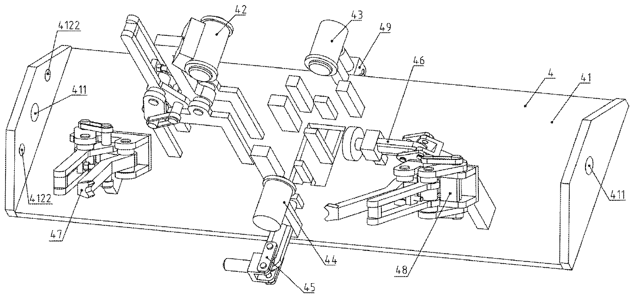
[0055] A spot-welding assembly jig for roller can ear base earring assembly, including a frame 2, a rotation limiting pin 3 and a turning assembly 4;

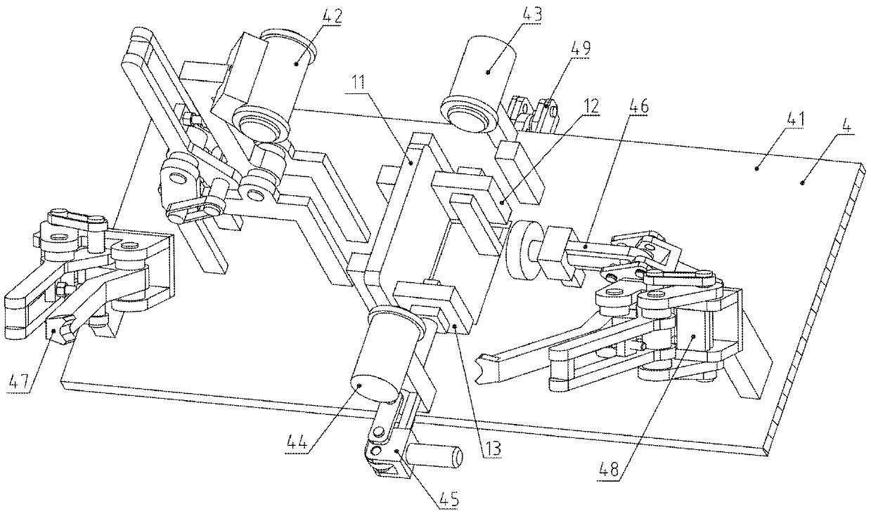
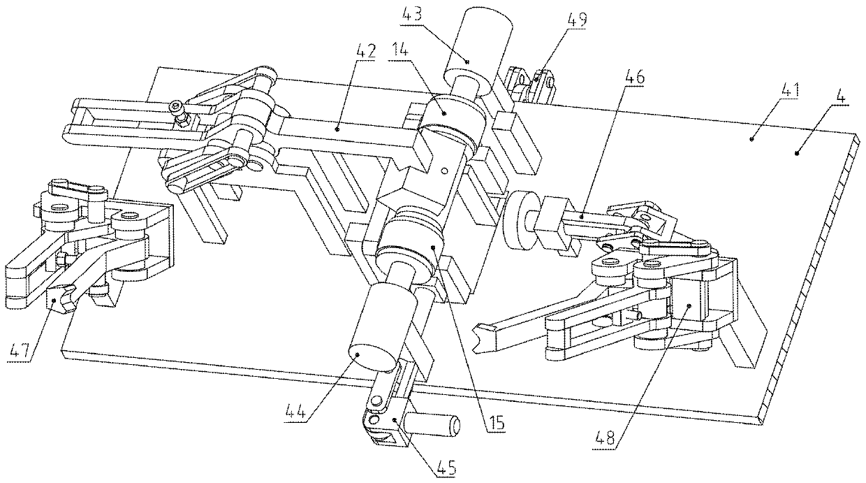
[0056] The overturn assembly 4 includes an overturn disc 41, a locating pin assembly 42 in the sleeve, a locating pin assembly 43 behind the sleeve, a locating pin assembly 44 before the sleeve, a front side plate quick clamp 45, a left side plate quick clamp 46, a right Plate oblique pressure quick clamp 47, left side plate oblique pressure quick clamp 48 and rear side plate rear hook quick clamp 49;

[0057]The two ends of overturning disk 41 are provided with overturning installation hole 411, and the axis line of overturning installation hole 411 is horizontally arranged; Just behind the installation hole 411 is provided with a rear limiting rotation hole 4122; by making the overturn installation hole 411 cooperate with the pin shaft on the frame 2, the overturn disc 41 and t...


PUM


Abstract

The invention belongs to the technical field of mine mechanical making equipment, and relates to a spot welding assembly tool clamp for a roller cage shoe base lug ring assembly. Three hydraulic cylinders on a sleeve middle positioning pin assembly, a sleeve rear positioning pin assembly and a sleeve front positioning pin assembly precisely position a lug ring rear single ring and a lug ring frontsingle ring, a front side plate rapid clamp, a left side plate rapid clamp, a right side plate inclined pressing rapid clamp, a left side plate inclined pressing rapid clamp and a rear side plate rear hook rapid clamp use dead points of a plane four-rod mechanism or a guide rod mechanism for pressing and positioning all side plates, and a turnover disc rotates by half circle to facilitate weldingof the inner side welding line. Compared with giant manual hydraulic pressure, it can be ensured that the lug ring rear single ring and the lug ring front single ring can be precisely positioned, andmold retreating can be facilitated; the tool is used for determining the relative size of the workpiece, compared with marking line scribing, the size determining is more precise, the produced part is unified in size, labor force is reduced, work efficiency is improved, the work principle of the dead points of the rapid clamps is used, use is convenient, the pressing force can be increased, and work efficiency is improved.

Description

technical field [0001] The invention belongs to the technical field of mining machinery manufacturing equipment, and relates to manufacturing equipment for roller can ears, in particular to a pairing jig for a spot welding group of earring components of a roller can ear base. Background technique [0002] The Roller Can Ear Base Earring Assembly includes the Earring Right Panel, Earring Back Side Panel, Earring Front Side Panel, Earring Back Single, Earring Front Single, and Earring Left Panel. Among them, the axis line of the inner hole of the rear single ring of the earring and the axis line of the inner hole of the front single ring of the earring are located on the same straight line, and the same straightness tolerance requirements are relatively high. The axis line of the rear single ring of the earring or the front single ring of the earring The axial center line of the earring is set in the front and back horizontal direction, and there is a certain distance between ...

Claims


Application Information

Patent Timeline
IPC IPC(8): B23K11/36B23K37/04
CPCB23K11/36B23K37/0443
Inventor 不公告发明人
Owner HEFEI LONGTUTEM INFORMATION TECH CO LTD
Why Eureka
Try Eureka