Engine valve mechanism and horizontally opposed double-cylinder engine

A gas distribution mechanism and engine technology, which is applied in the direction of engine components, machines/engines, valve devices, etc., can solve the problems of unfavorable engine size reduction and light weight, large valve angle of the gas distribution mechanism, and increased development and maintenance costs. Achieve low development and maintenance costs, improve the power-to-weight ratio, and benefit the overall lightweight effect

Inactive Publication Date: 2019-11-12
CHONGQING IONCIN NAVIGATION ENGINE MFG C0 LTD
View PDF3 Cites 5 Cited by
  • Summary
  • Abstract
  • Description
  • Claims
  • Application Information

AI Technical Summary

Problems solved by technology

[0004] The camshaft of the existing two-cylinder four-stroke engine valve mechanism is often arranged parallel to the crankshaft, and is connected by a gear or chain transmission. The structure is not compact, the weight is heavy, the transmission efficiency is reduced, and the development and maintenance costs are increased; Columns, tappets, etc. are often built into the engine cavity, which is not conducive to the reduction in size and weight of the engine; and the valve angle of the valve mechanism is relatively large, resulting in increased air intake resistance and low air intake efficiency of the engine

Method used


Image

  • Engine valve mechanism and horizontally opposed double-cylinder engine
  • Engine valve mechanism and horizontally opposed double-cylinder engine
  • Engine valve mechanism and horizontally opposed double-cylinder engine

Examples


Embodiment Construction

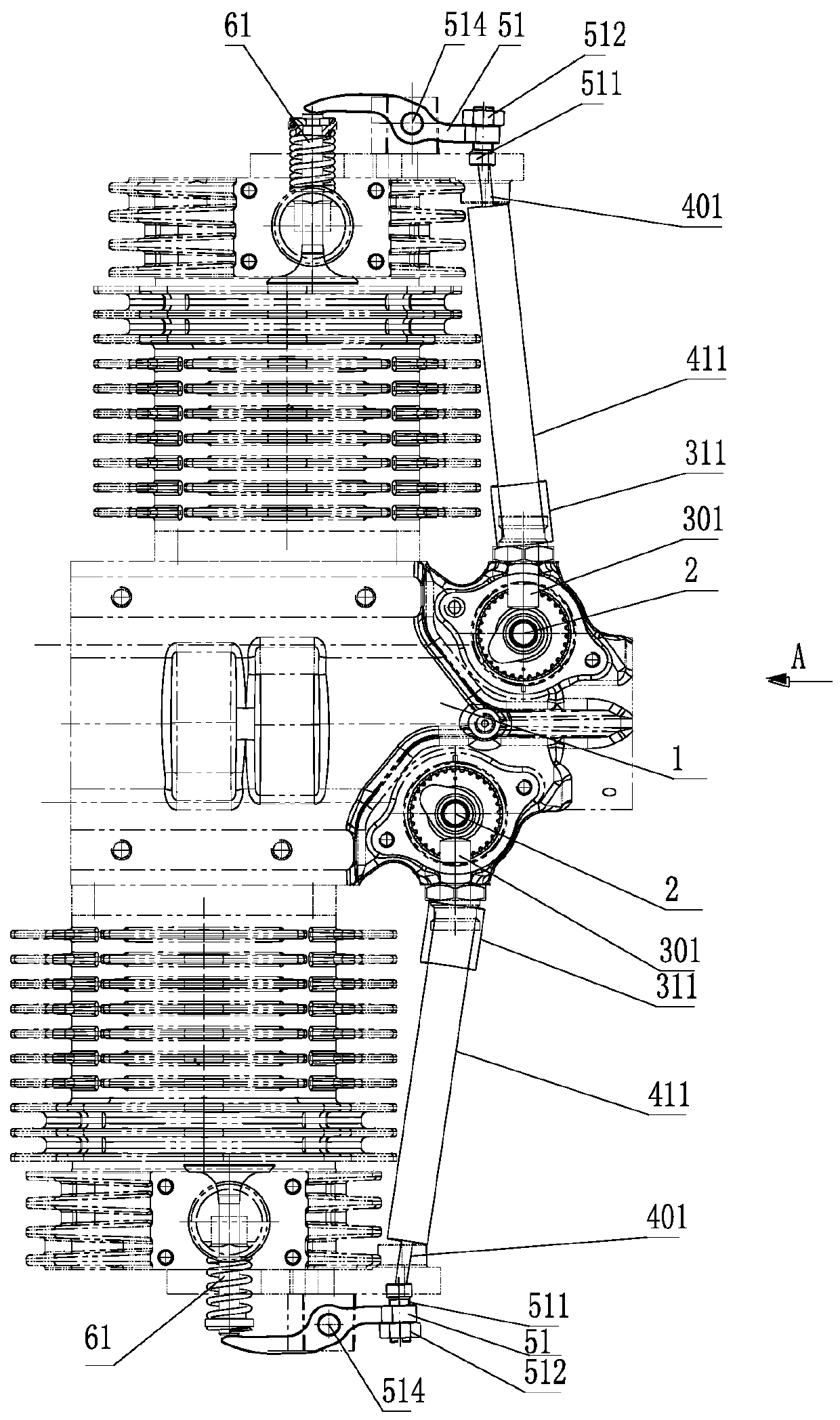
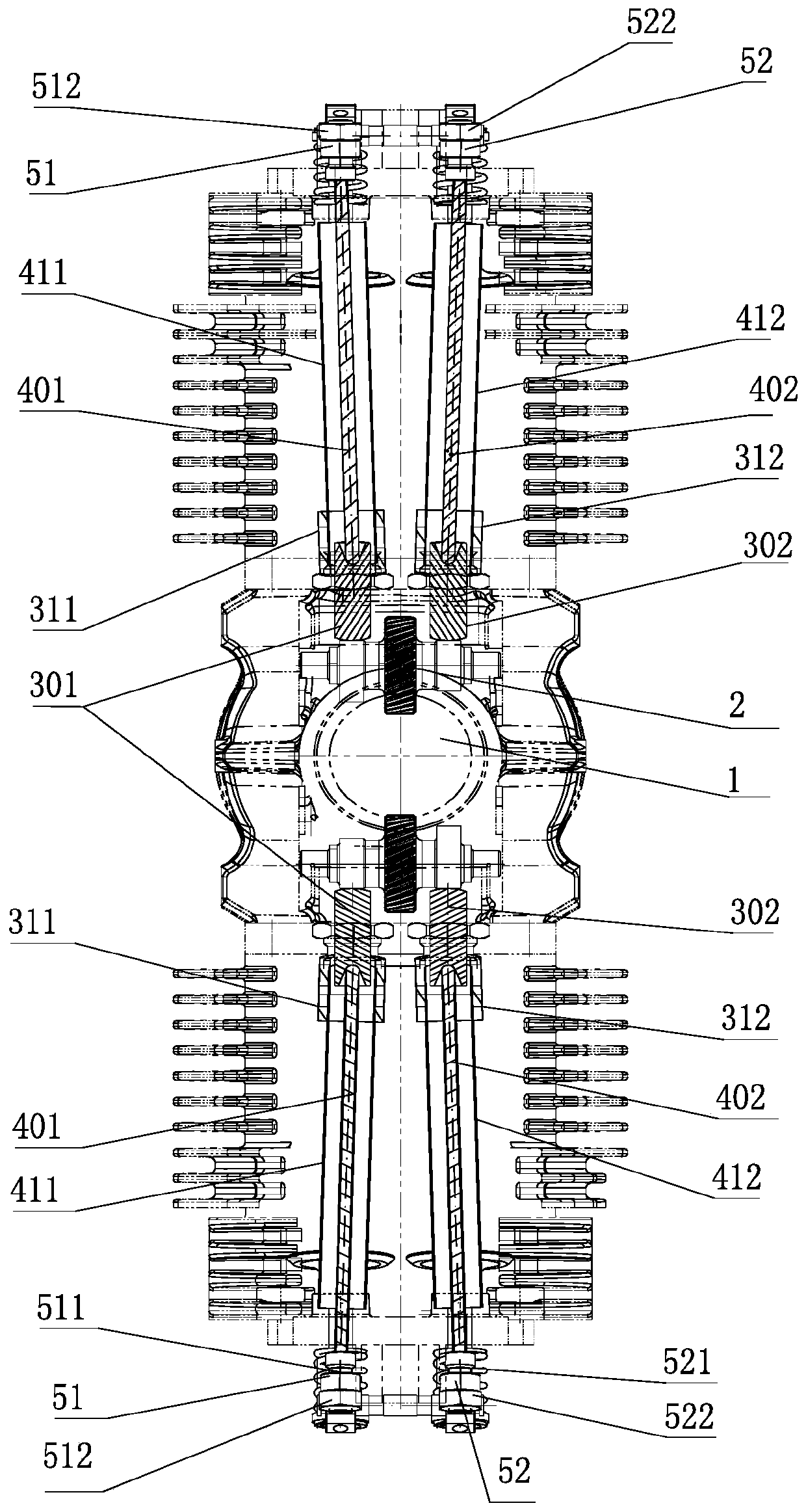
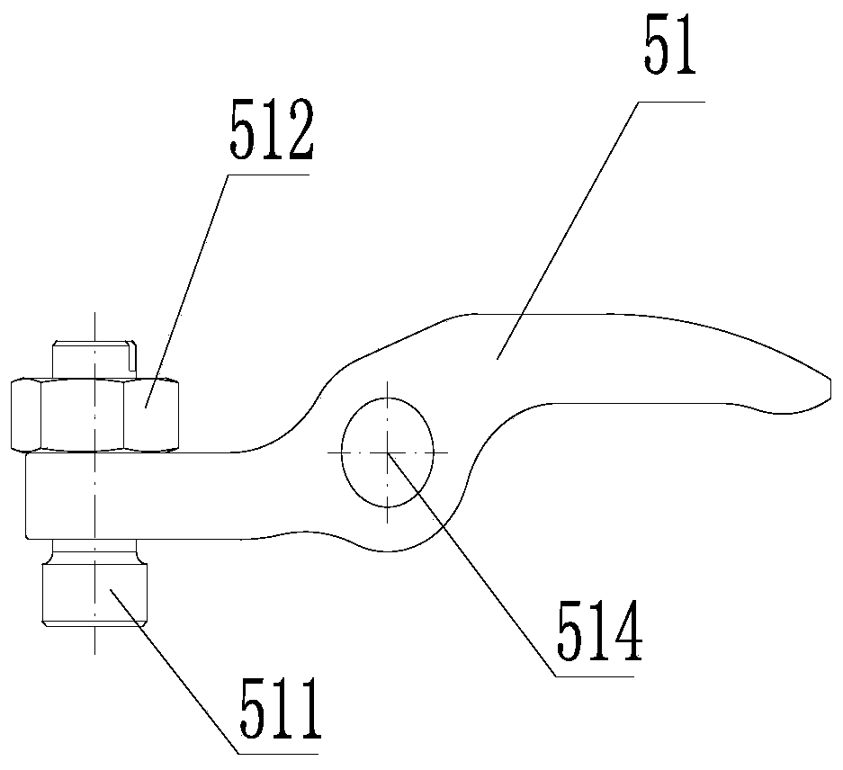
[0026] figure 1 Is a schematic diagram of the structure of the present invention, figure 2 for figure 1 Schematic diagram of the A-direction structure, image 3 Is a schematic diagram of the structure of the rocker arm assembly of the present invention, Figure 4 Is a cross-sectional view of the rocker arm assembly of the present invention, Figure 5 Is an isometric view of the camshaft driving mode of the present invention, Image 6 Is the isometric test chart of the camshaft of the present invention, Figure 7 It is a schematic diagram of the cylinder head of the present invention, as shown in the figure: the engine valve mechanism of this embodiment includes a drive assembly and a valve assembly driven by the drive assembly; the drive assembly includes a camshaft arranged perpendicular to the crankshaft 1 space 2. The tappet driven by the cam, the tappet driven by the tappet, and the valve rocker arm assembly that swings and drives the valve assembly under the drive of the ta...


PUM


Abstract

The invention relates to an engine valve mechanism and a horizontally opposed double-cylinder engine. The engine valve mechanism comprises a drive assembly and a valve assembly driven by the drive assembly, wherein the drive assembly comprises a camshaft vertical to a crankshaft space, tappets driven by a cam, tappet rods driven by the tappets and a valve rocker arm assembly which swings and drives the valve assembly under drive of the tappet rods; a crankshaft with timing driving teeth directly drives the camshaft with timing driven teeth, and then the tappets and the tappet rods drive valverocker arms to drive an intake valve and an exhaust valve to open and close back and forth. The engine valve mechanism avoids gear or chain transmission connection modes, and has higher transmission efficiency and lower engine development and maintenance costs. The tappets and the tappet rods are arranged outside an engine body, so that size of an engine is reduced, the engine is lightweight, andthe power to weight ratio of the engine is increased; besides, the included angle between the valves of the valve mechanism is 0, intake resistance can be reduced to the greatest extent, intake efficiency is improved, the application field of the engine is expanded, and the structure is simple and compact.

Description

Technical field [0001] The invention relates to the field of engine gas distribution, in particular to an engine gas distribution mechanism and a horizontally opposed two-cylinder engine. Background technique [0002] The engine's valve mechanism is to regularly open and close the intake and exhaust valves of each cylinder in accordance with the requirements of the working cycle and ignition sequence carried out in each cylinder of the engine to make fresh combustible mixture (gasoline engine) or air (diesel engine) A device that can enter the cylinder in time and exhaust exhaust gas from the cylinder in time. [0003] Most of the existing engines are two-cylinder four-stroke engines. The working cycle of a four-stroke engine consists of 4 piston strokes, namely intake stroke, compression stroke, power stroke and exhaust stroke. In this process, the piston reciprocates up and down for four strokes, and the corresponding crankshaft rotates two times. Compared with two-stroke engin...

Claims


Application Information

Patent Timeline
Patent Type & Authority Applications(China)
IPC IPC(8): F01L1/047F01L1/14F01L1/18F02B75/24
CPCF01L1/047F01L1/14F01L1/181F02B75/243
Inventor 林成石晓东刘小林熊常兵黄国斌
Owner CHONGQING IONCIN NAVIGATION ENGINE MFG C0 LTD
Why Eureka
Try Eureka