Plunger pump driven by linear motor

A technology of linear motors and plunger pumps, which is applied to components of pumping devices for elastic fluids, machines/engines, pumps, etc., can solve problems such as large friction and wear, unstable discharge pressure, and low system efficiency, and achieve Reduced friction and wear, convenient maintenance and high system efficiency

Pending Publication Date: 2019-11-12
YANTAI JEREH PETROLEUM EQUIP & TECH CO LTD
View PDF0 Cites 101 Cited by
  • Summary
  • Abstract
  • Description
  • Claims
  • Application Information

AI Technical Summary

Problems solved by technology

This kind of rotary drive plunger pump has the following problems: the traditional rotary drive plunger pump has many intermediate transmission links, high friction and wear, and low system efficiency; the structure is complex, the manufacturing process is difficult, the cost is high, there are many vulnerable parts, and failures occur The probability of high risk is high, and maintenance is inconvenient; the plunger speed varies greatly, the displacement

Method used


Image

  • Plunger pump driven by linear motor
  • Plunger pump driven by linear motor
  • Plunger pump driven by linear motor

Examples


Embodiment Construction

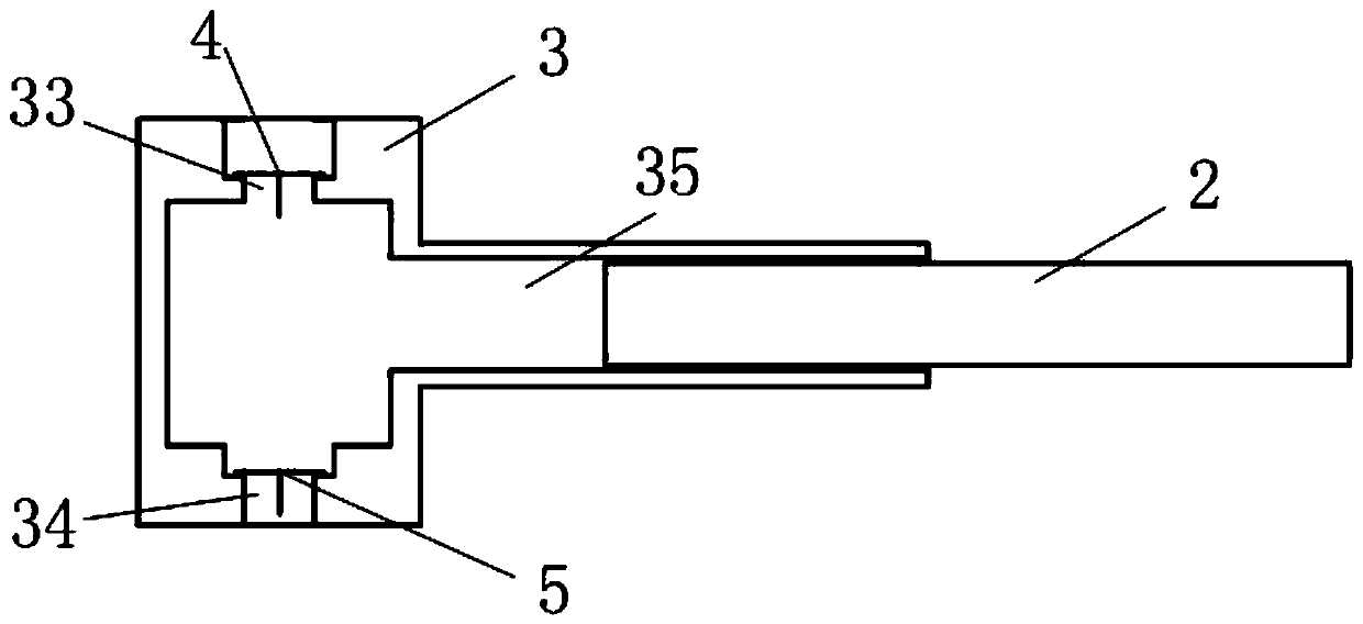
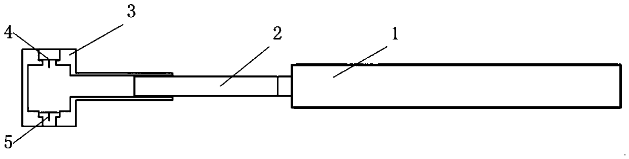
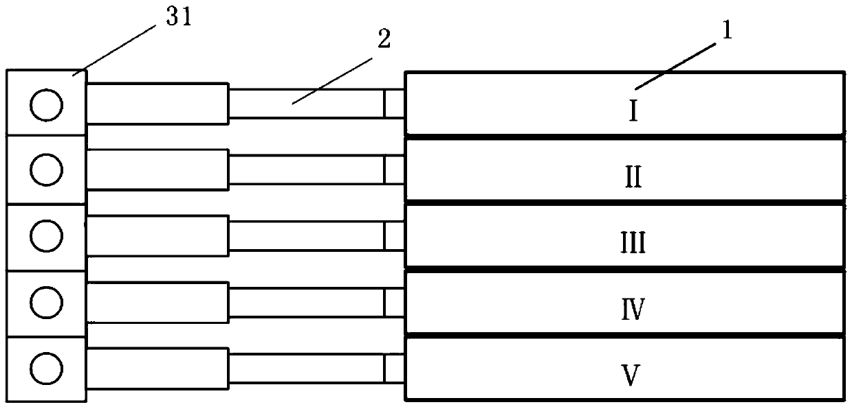
[0022] Such as Figures 1 to 10 As shown, a plunger pump driven by a linear motor includes a linear motor and a liquid end assembly, the linear motor is a single-acting linear motor 1 or a double-acting linear motor 9, and the linear motor and the liquid end assembly The fluid end assembly includes a plunger 2 , a valve box 3 , an upper valve body 4 and a lower valve body 5 , and the valve box 3 is a single-cylinder combined valve box 31 or a multi-cylinder valve box 32 . The single-cylinder combined valve box 31 includes a two-cylinder combined valve box, a three-cylinder combined valve box, a four-cylinder combined valve box, a five-cylinder combined valve box, a six-cylinder combined valve box and a seven-cylinder combined valve box. box. The multi-cylinder valve box 32 includes a two-cylinder valve box, a three-cylinder valve box, a four-cylinder valve box, a five-cylinder valve box, a six-cylinder valve box and a seven-cylinder valve box. Each cylinder of the valve box ...


PUM


Abstract

The invention discloses a plunger pump driven by a linear motor. The plunger pump is driven by the linear motor, and a motion rule of an assembly is controlled by controlling a motion rule of the linear motor, so that the disadvantages of an existing plunger pump are overcome, and the advantage of the plunger pump is exerted to the maximum extent.

Description

technical field [0001] The invention relates to the technical field of plunger pumps, in particular to a plunger pump driven by a linear motor. Background technique [0002] Traditional plunger pumps generally change the rotary motion of the prime mover into linear reciprocating motion of the plunger through the crank linkage mechanism, so that the liquid is intermittently sucked into the pump cylinder and discharged from the pipeline at high pressure to achieve the purpose of conveying the liquid. This kind of rotary drive plunger pump has the following problems: the traditional rotary drive plunger pump has many intermediate transmission links, high friction and wear, and low system efficiency; the structure is complex, the manufacturing process is difficult, the cost is high, there are many vulnerable parts, and failures occur The probability of high risk is high, and maintenance is inconvenient; the plunger speed varies greatly, the displacement of the plunger pump fluct...

Claims


Application Information

Patent Timeline
IPC IPC(8): F04B17/03F04B53/10F04B53/00
CPCF04B17/03F04B53/001F04B53/109
Inventor 崔海萍王继鑫李海龙
Owner YANTAI JEREH PETROLEUM EQUIP & TECH CO LTD
Why Eureka
Try Eureka