Integrated test device and test method for low-temperature radiometer
A low-temperature radiation and integrated device technology, which is applied in the field of low-temperature radiometer test integrated devices, can solve problems such as low test accuracy and complex structure, and achieve the effects of eliminating response differences, improving detection accuracy, and eliminating poor test accuracy of stray light
- Summary
- Abstract
- Description
- Claims
- Application Information
AI Technical Summary
Problems solved by technology
Method used
Image
Examples
Embodiment 1
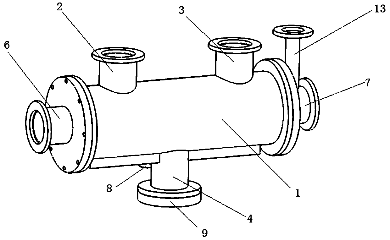
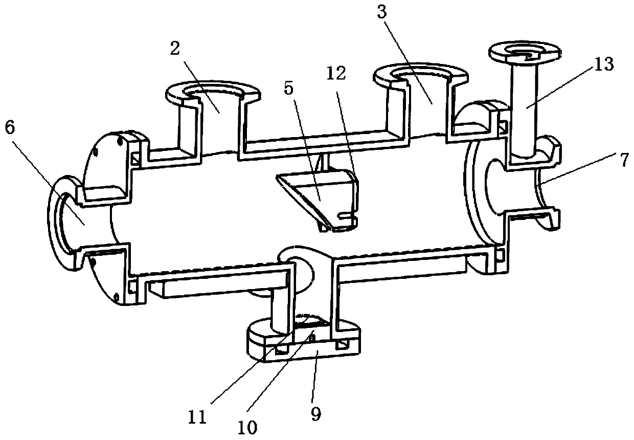
[0044] to combine figure 1 with figure 2 , a test integrated device for cryogenic radiometers, comprising a main cylinder 1, the upper part of the main cylinder 1 is provided with a Brewster window transmittance test window 2 and a stray light test window 3, and the lower part of the main cylinder 1 is provided with A vacuum flange 4 is installed on a four-quadrant detector, and an off-axis parabolic reflector 5 is arranged inside the main cylinder.
[0045] The front end of the main cylinder 1 is connected with a front vacuum flange 6 , and the rear end of the main cylinder 1 is connected with a rear vacuum flange 7 .
[0046] Brewster window transmittance test window 2, stray light test window 3 and four-quadrant detector installation vacuum flange 4 are all communicated with the main cylinder.
[0047] The side of the four-quadrant detector installation vacuum flange 4 is provided with an aviation plug interface 8, the bottom of the four-quadrant detector installation va...
Embodiment 2
[0054] A method for aligning and debugging an incident beam of a low temperature radiometer, using the integrated test device for a low temperature radiometer described in Embodiment 1.
[0055] The method includes the following steps:
[0056] Step 1: Complete the spatial filtering of the incident light and stabilize the power control, open the cold shields at all levels of the low temperature radiometer, remove the black body cavity of the low temperature radiometer, and adjust the direction of the incident light so that the incident light passes through the center of the black body cavity mounting seat.
[0057] Step 2: Reassemble the black body cavity and cold shields of all levels of the cryoradiometer. The rear vacuum flange 7 is installed together with the light hole of the outer shield of the cryoradiometer through the vacuum baffle valve.
[0058] Step 3: Observe whether the incident light passes through the center of the through hole of the off-axis parabolic reflect...
Embodiment 3
[0062] After completing the alignment in Example 2, a Brewster window transmittance test was performed.
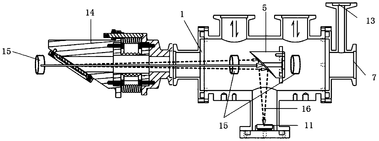
[0063] to combine image 3 , a low temperature radiometer Brewster window transmittance test method, comprising the following steps:
[0064] Step 1: Install Brewster window 14 on front vacuum flange.
[0065] Step 2: Install a two-dimensional electric translation platform on one side of the test integration device. A photodetector 15 is arranged on the two-dimensional electric translation platform, and the photodetector can move on the two-dimensional electric translation platform.
[0066] Step 3: The photodetector extends from the Brewster window transmittance test window, and adjusts the inclination angle of the Brewster window and the polarization state of the incident light until the optimum transmittance value of the Brewster window is obtained.
[0067] Step 4: The photodetector first tests the optical power value P at the front end of the Brewster window 1 , af...
PUM
 Abstract
Description
Claims
Application Information
 - R&D
- Intellectual Property
- Life Sciences
- Materials
- Tech Scout
- Unparalleled Data Quality
- Higher Quality Content
- 60% Fewer Hallucinations
Browse by: Latest US Patents, China's latest patents, Technical Efficacy Thesaurus, Application Domain, Technology Topic, Popular Technical Reports.
© 2025 PatSnap. All rights reserved.Legal|Privacy policy|Modern Slavery Act Transparency Statement|Sitemap|About US| Contact US: help@patsnap.com


