

Swing polarizer type polarization imaging measuring device and method
A polarization imaging and measurement device technology, which is applied to measurement devices, polarization spectroscopy, optical device exploration, etc., can solve problems such as insufficient polarization detection, and achieve the effects of improving sampling speed, simple operation, and solving fast measurement problems.
- Summary
- Abstract
- Description
- Claims
- Application Information
AI Technical Summary
Problems solved by technology
Method used
Image

Examples
Embodiment 1
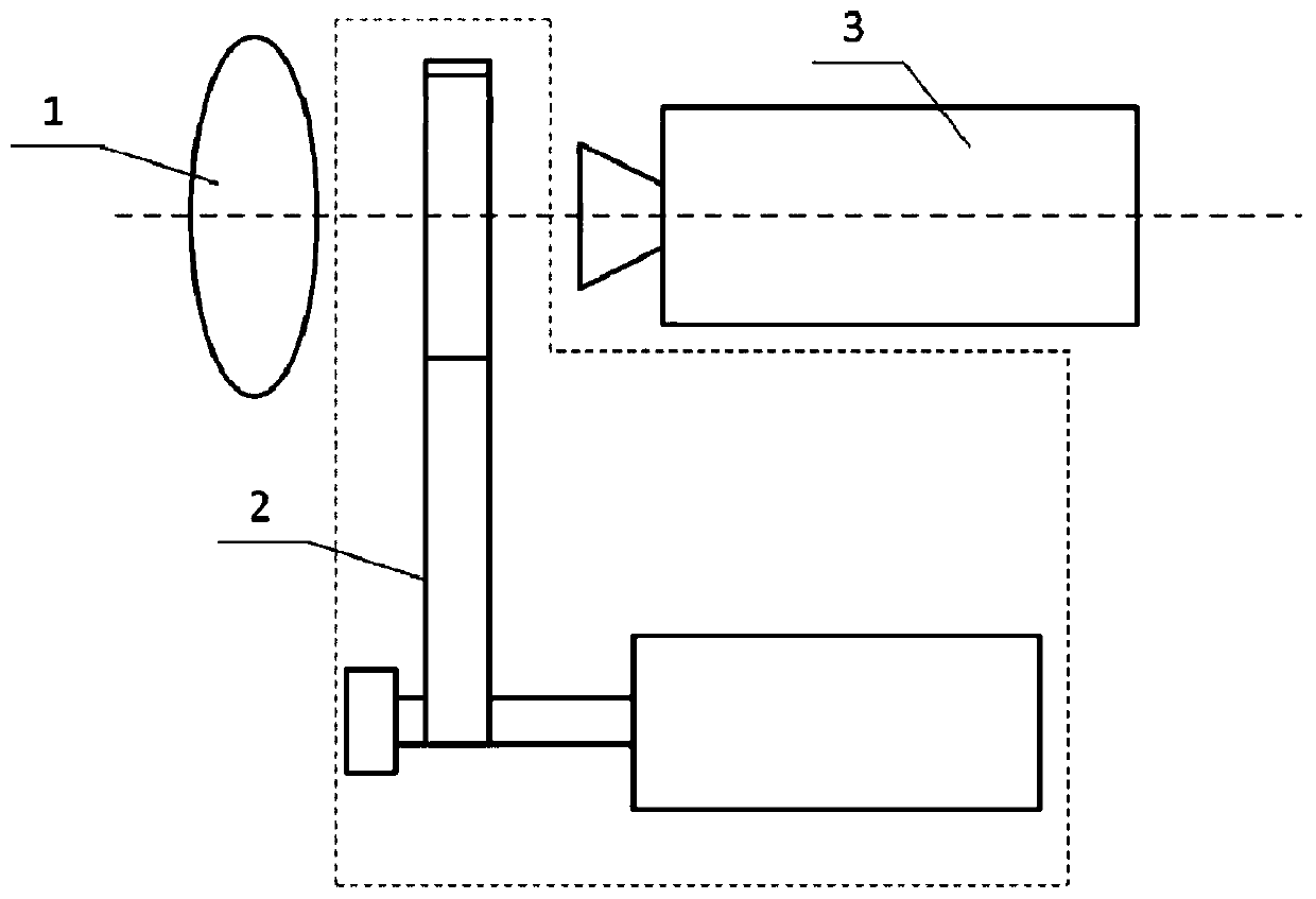
[0034] Such as figure 1 As shown, a swinging polarizer-type polarization imaging measurement device provided by an embodiment of the present invention includes a lens module 1, a polarization module 2, a detection module 3 and a control module ( figure 1 not shown). Wherein, the lens module 1 includes an optical lens for imaging a target scene, and the detection module 3 includes a detector for receiving light emitted by the optical lens. The central axis of the detector coincides with the central axis of the optical lens to receive light. Preferably, the lens module 1 also includes a lens holder for setting the optical lens, and the detection module 3 also includes a detector holder for setting the detector, and an adjustable bracket is preferably arranged between the lens holder and the detector holder. The slide rail is used to locate the relative position of the detector and the optical lens.
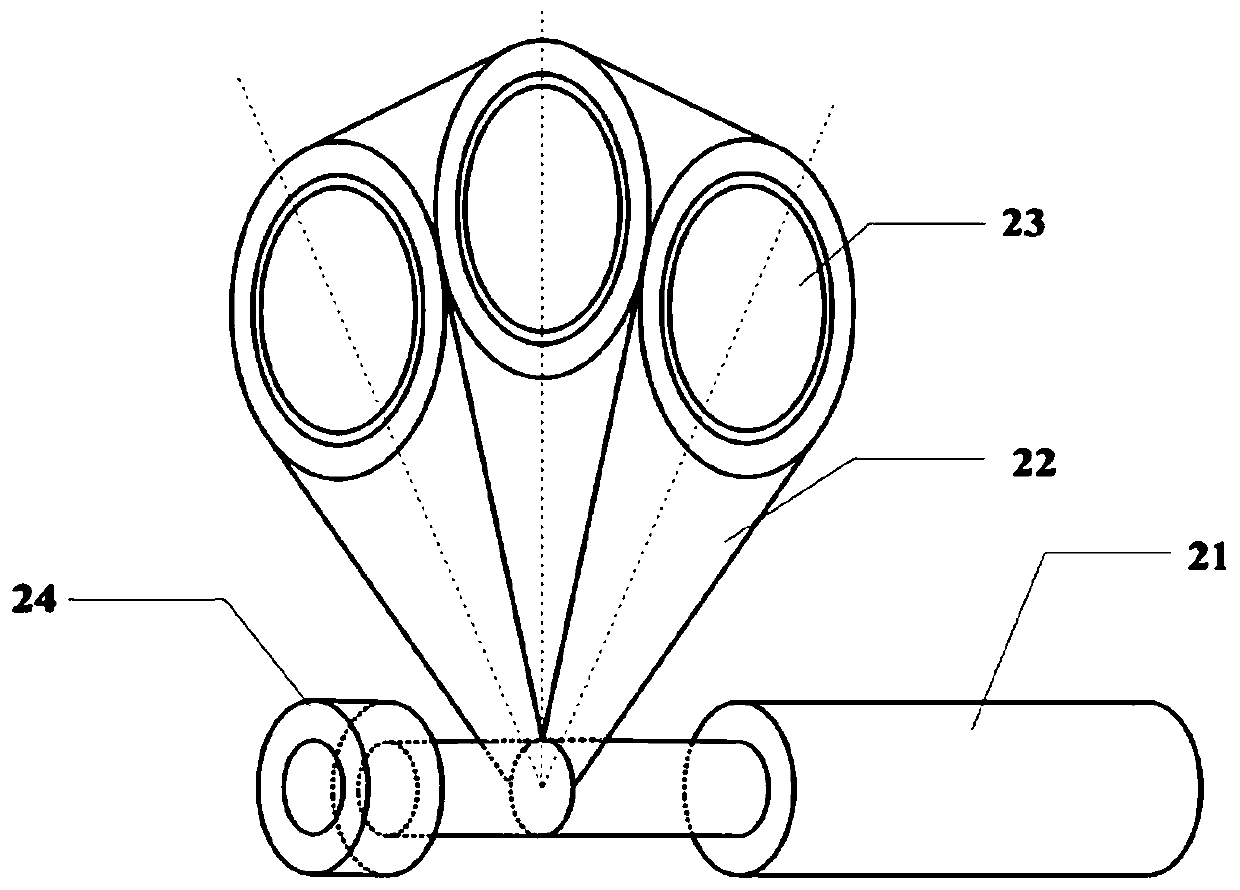
[0035] Such as figure 1 and figure 2 As shown, the polarization module 2 inc...
Embodiment 2
[0049] For the above-mentioned swinging polarizer-type polarization imaging measurement device, the present invention also provides a swinging polarizer-type polarization imaging measurement method, using the swinging polarizer-type polarization imaging measurement device as described in any one of the above to perform polarization imaging measurement, specifically Including the following steps:
[0050] S1. Arrange and calibrate a swinging polarizer-type polarization imaging measurement device on one side of the target scene.
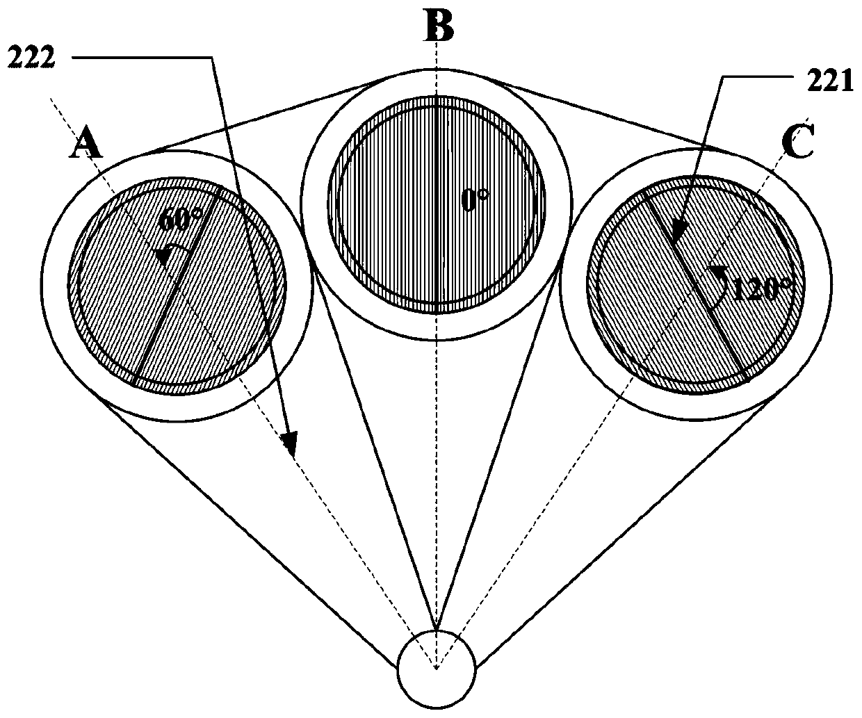
[0051] Among them, the calibration includes adjusting the relative positions of the lens module 1, the polarization module 2, and the detection module 3, so that the central axis of the detector coincides with the central axis of the optical lens, and any polarizer 23 can be turned to make its own central axis coincide with the detection axis. The measuring position where the central axes of the detector and the optical lens coincide, and when the cent...
Embodiment 3
[0068] Such as Figure 1 to Figure 4 As shown, the third embodiment is basically the same as the first embodiment, and the similarities will not be repeated. The difference lies in:
[0069] The swinging polarizer polarization imaging measurement device uses three quartz wire grid polarizers with the same specifications, the effective diameter is 25.4mm, the effective wavelength range is from visible to short-wave infrared, that is, 350-2500nm, the transmittance is greater than 80%, and the extinction The ratio is 1000:1. After the quartz wire grid polarizer is clamped and installed on the balance wheel through the pressure ring, the difference between the effective light aperture and the effective diameter of the polarizer is no more than 4mm. The minimum value of the cycle number n of the reciprocating swing is 25. A CCD detector is used for radiation intensity image acquisition.
[0070] During operation, the polarization module and the detection module work synchronously...
PUM
 Abstract
Description
Claims
Application Information