Manual test base with upper slider structure

A technique of manual testing and testing the base, which is applied in the direction of electronic circuit testing, measuring electronics, measuring devices, etc. It can solve the problems of reducing test efficiency, affecting the test results of high-pixel optical chips, and increasing operating steps, so as to avoid partial extrusion of chips , Guarantee the reliability of the test and avoid the effect of relative deviation

Pending Publication Date: 2019-11-12
SUZHOU CHUANGRUI MACHINERY & ELECTRICAL TECH
View PDF0 Cites 0 Cited by
  • Summary
  • Abstract
  • Description
  • Claims
  • Application Information

AI Technical Summary

Problems solved by technology

[0010] However, since the flap is turned over, when the pressure plate and the chip first come into contact, they can only touch a part of the side of the chip, so that the relative sliding between the pressure plate and the chip may cause the chip to shift, affecting the chip and the chip fixed on the upper cover. The position between the upper lens holes directly affects the test results of high-pixel optical chips
[0011] There is also a manual test screw cap socket, the overall structure is separated from top to bottom, and it is relatively inconvenient to take and place; after the screw cap is pressed, it needs to be tightened, which increases the operation steps and reduces the test efficiency, and the screw cap structure is relatively flip structure. More parts and more complicated structure

Method used


Image

  • Manual test base with upper slider structure
  • Manual test base with upper slider structure
  • Manual test base with upper slider structure

Examples


Embodiment 1

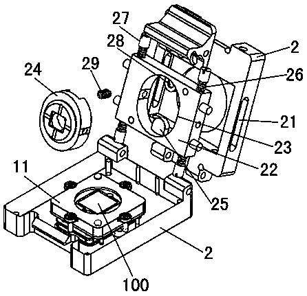
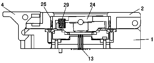
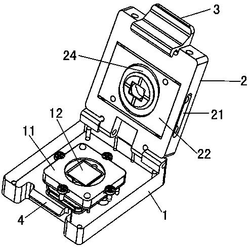
[0027] A manual test base provided with an upper slider structure, such as Figure 1-3 As shown, including the test base 1 and the upper cover 2.

[0028] Specifically, the upper cover 2 is hinged on one side of the test base 1 and can be flipped and pressed together with the test base 1. The test base 1 is provided with a floating plate structure 11. The floating plate structure is fixed to the test base by bolts, and the floating plate The plate structure is surrounded by a closed whole.

[0029] A chip groove 12 is provided in the floating plate structure 11 for setting the chip 100. The test probe 13 is also arranged in the floating plate structure and acts on the bottom side of the chip groove 12. Specifically, the test probe 13 is a micro-probe (POGO PIN) to export the signal of the product.

[0030] In order to realize that there is no relative between the chip and the pressure plate after the contact, the slide groove 21 at the side end of the sliding upper cover 2 i...


PUM


Abstract

The invention discloses a manual test base with an upper slider structure, comprising a test base and an upper cover, wherein the upper cover is hinged to one side of the test base and can be flippedand pressed with the test base, a floating plate structure is disposed on the test base, a chip slot is formed in the floating plate structure, a slider is arranged in the middle of the upper cover through a chute on a side, a pressure plate is rotatably disposed in the middle of the slider through a pressure plate groove, the pressure plate is opposite to the chip slot when the upper cover is closed, a stop tongue is disposed in the pressure plate groove such that the pressure plate is inclined, and a return spring and an adjusting screw are symmetrically disposed on the upper and lower sidesof the slider. The manual test base has a simple structure; by using a slider structure on the upper cover, the pressure plate and a chip do not slide relative to each other when the pressure plate is rotated to press the chip; and the pressure plate is inclined to ensure that the contact planes of the pressure plate and the chip are nearly parallel, thereby avoiding local extrusion to the chip and ensuring the test reliability.

Description

technical field [0001] The invention relates to the field of test bases, in particular to a manual test base provided with an upper slider structure. Background technique [0002] The optical camera chip (CIS) and its camera module (CMOS) are widely used in industrial, medical and consumer fields. With the requirements of end users for image processing and the development of high-pixel image acquisition and analysis technology, this product has gradually replaced the original glass optical lens in many fields. [0003] The tens of millions of optical chip modules is a major development trend in the CIS and CMOS industries. At present, this kind of chip is mainly used in satellites, high-altitude reconnaissance aircraft and high-pixel smart cameras. With the product's packaging and testing process becoming more and more mature, the trend of application in high-definition cameras, surveillance cameras, mobile phone cameras and computer cameras will be unstoppable. [0004] I...

Claims


Application Information

Patent Timeline
Patent Type & Authority Applications(China)
IPC IPC(8): G01R31/28G01R1/04
CPCG01R1/0408G01R31/2851
Inventor 刘鑫培朱小刚柳慧敏
Owner SUZHOU CHUANGRUI MACHINERY & ELECTRICAL TECH
Why Eureka
Try Eureka