
Electronic unit

A technology of electronic units and electronic components, applied in the direction of electrical components, printed circuits, printed circuits, etc.

Active Publication Date: 2019-11-12
C & E PANYIN CO LTD
View PDF4 Cites 0 Cited by
  • Summary
  • Abstract
  • Description
  • Claims
  • Application Information

AI Technical Summary

Problems solved by technology

This entails the additional disadvantage that cooling of the electronic components is thus only limited

Method used


Image

  • Electronic unit
  • Electronic unit
  • Electronic unit

Examples


Embodiment Construction

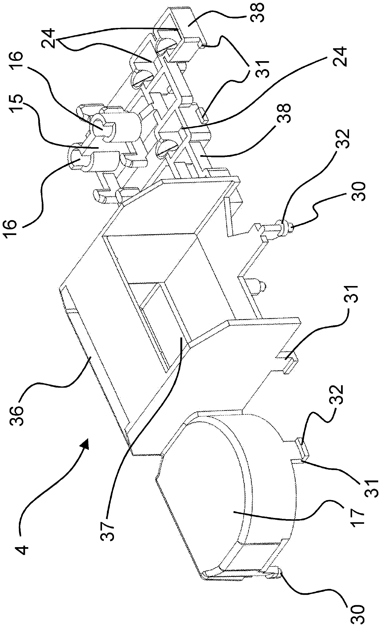
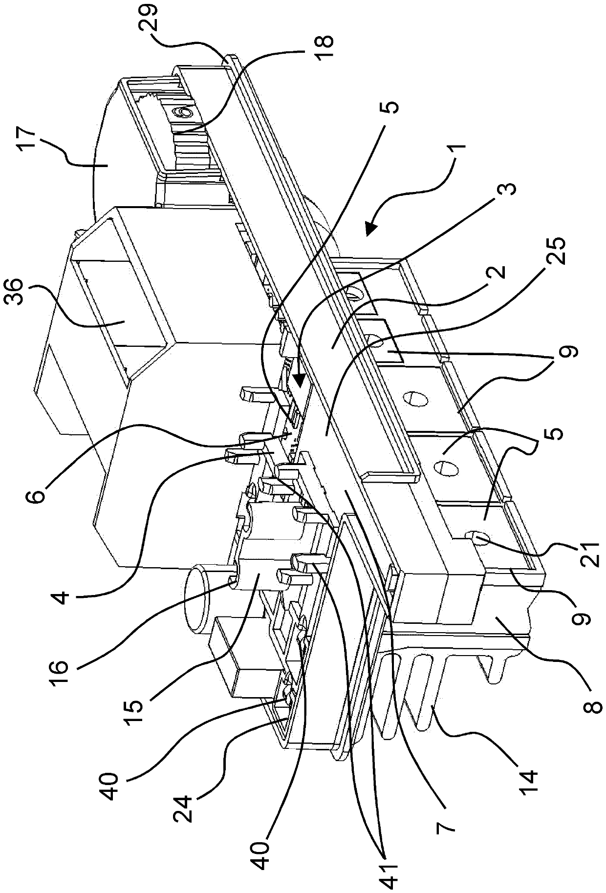
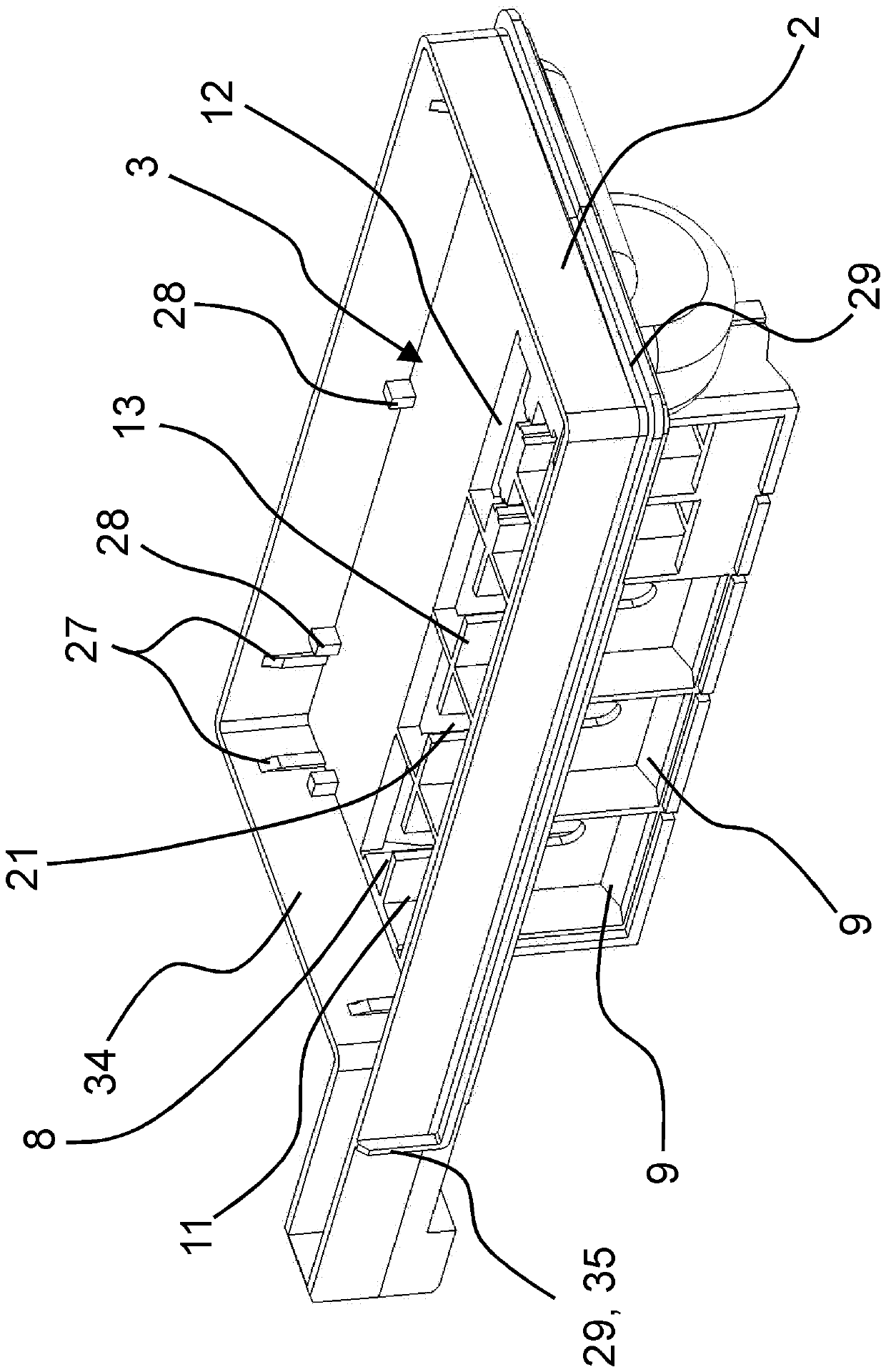
[0024] figure 1 Electronics unit 1 for a hand-held power tool is shown in a perspective view. In this case, the electronics unit 1 has an assembly frame 2 which includes a receiving space 3 and a casting mask 4 . A circuit board 6 carrying a plurality of electronic components 5 is inserted into the receiving space 3 , wherein a part of the electronic components 5 is cast on the circuit board 6 by means of a casting mass 7 and thus protected from Mechanical damage and protection against dirt, in particular conductive metal dust, from the working environment of the hand-held power tool. A shaft section 8 is formed on the mounting frame 2 with a plurality of insertion shafts 9 , which are oriented perpendicularly to the circuit board 6 . In this case, the further electronic component 5 is inserted into the insertion shaft 9 along the insertion direction 10 . The push-in wells 9 are arranged in the initial example shown in a first row 11 and in a second row 12 , the push-in wel...


PUM


Abstract

The invention relates to an electronic unit (1) for a hand-held power tool. The invention relates to an electronic unit (1) comprising a mounting frame (2), which has a receiving space (3) into whicha printed circuit board (6) carrying a plurality of electronic components (5) is inserted, and comprising at least one heat sink (14) for dissipating heat that occurs at the electronic components (5).A well-shaped section (8) with at least one push-in well (9) oriented perpendicular to the printed circuit board (6) is formed on the mounting frame (2) for receiving an electronic component (5) in apush-in direction (10). The at least one cooling body (14) is associated with the well-shaped section (8).

Description

technical field [0001] The invention relates to an electronics unit for a hand-held power tool with an assembly frame having a receiving space into which a printed circuit board carrying a plurality of electronic components is inserted, And the electronics unit has at least one heat sink for heat dissipation of heat losses occurring at the electronic components. Background technique [0002] Such an electronic unit is known, for example, from WO 2017 / 173000 A1, in which the electronic components are soldered to the circuit board. During assembly, the electronic components must first be placed on the circuit board individually before they can be soldered to the circuit board. A relatively high assembly effort is associated with this, which has a disadvantageous effect on the production time and thus also on the production costs of the electronics unit. Furthermore, the heat sink used in WO 2017 / 173000 A1, which is provided for dissipating the heat loss that occurs, has fast...

Claims


Application Information

Patent Timeline
Patent Type & Authority Applications(China)
IPC IPC(8): H05K7/14H05K7/20B25F5/00
CPCH05K7/1424H05K7/2039B25F5/00B25F5/008H05K7/20509H05K1/0203H05K1/181H05K5/064H05K7/1432H05K7/209H05K2201/066H05K2201/10409
Inventor C.沃尔弗罗姆W.迪尔内格
Owner C & E PANYIN CO LTD
Features
  • Generate Ideas
  • Intellectual Property
  • Life Sciences
  • Materials
  • Tech Scout
  • Unparalleled Data Quality
  • Higher Quality Content
  • 60% Fewer Hallucinations
Learn More