Supercharge Your Innovation With Domain-Expert AI Agents!

Secondary heat exchange type tunnel furnace

A secondary heat exchange and tunnel furnace technology, applied in the field of tunnel furnaces, can solve problems such as simple structure, poor safety, food contamination, dripping to the ground, etc., to reduce energy consumption, improve heat utilization, and dull and rough color Effect

Pending Publication Date: 2019-11-15
GUANGZHOU FUYA MACHINERY
View PDF0 Cites 1 Cited by
  • Summary
  • Abstract
  • Description
  • Claims
  • Application Information

AI Technical Summary

Problems solved by technology

[0003] The flame-resistant tunnel furnace mainly uses the heat generated by the burner to directly enter the furnace in the form of air and act on the product. However, there are the following disadvantages in heating food in this way: First, the combustion exhaust gas directly contacts the food, causing food pollution. If The fuel is diesel and liquefied petroleum gas; the second is that the surface color of the product baked by this combustion method is dull and rough; the third is that during the whole furnace baking process, the furnace will produce moisture dripping to the ground, because the moisture generated by the combustion directly enters the furnace , alternating cold and hot will produce condensed water
The combustion system adopting the indirect hot air method avoids the direct contact of combustion waste gas with food, causing food pollution, but its combustion efficiency is too low, the fuel utilization rate is only 35-50%, and the structure is simple and the safety is poor

Method used


Image

  • Secondary heat exchange type tunnel furnace
  • Secondary heat exchange type tunnel furnace
  • Secondary heat exchange type tunnel furnace

Examples


Embodiment Construction

[0035] Below, the present invention will be further described in conjunction with the accompanying drawings and specific implementation methods. It should be noted that, under the premise of not conflicting, the various embodiments or technical features described below can be combined arbitrarily to form new implementations. example.

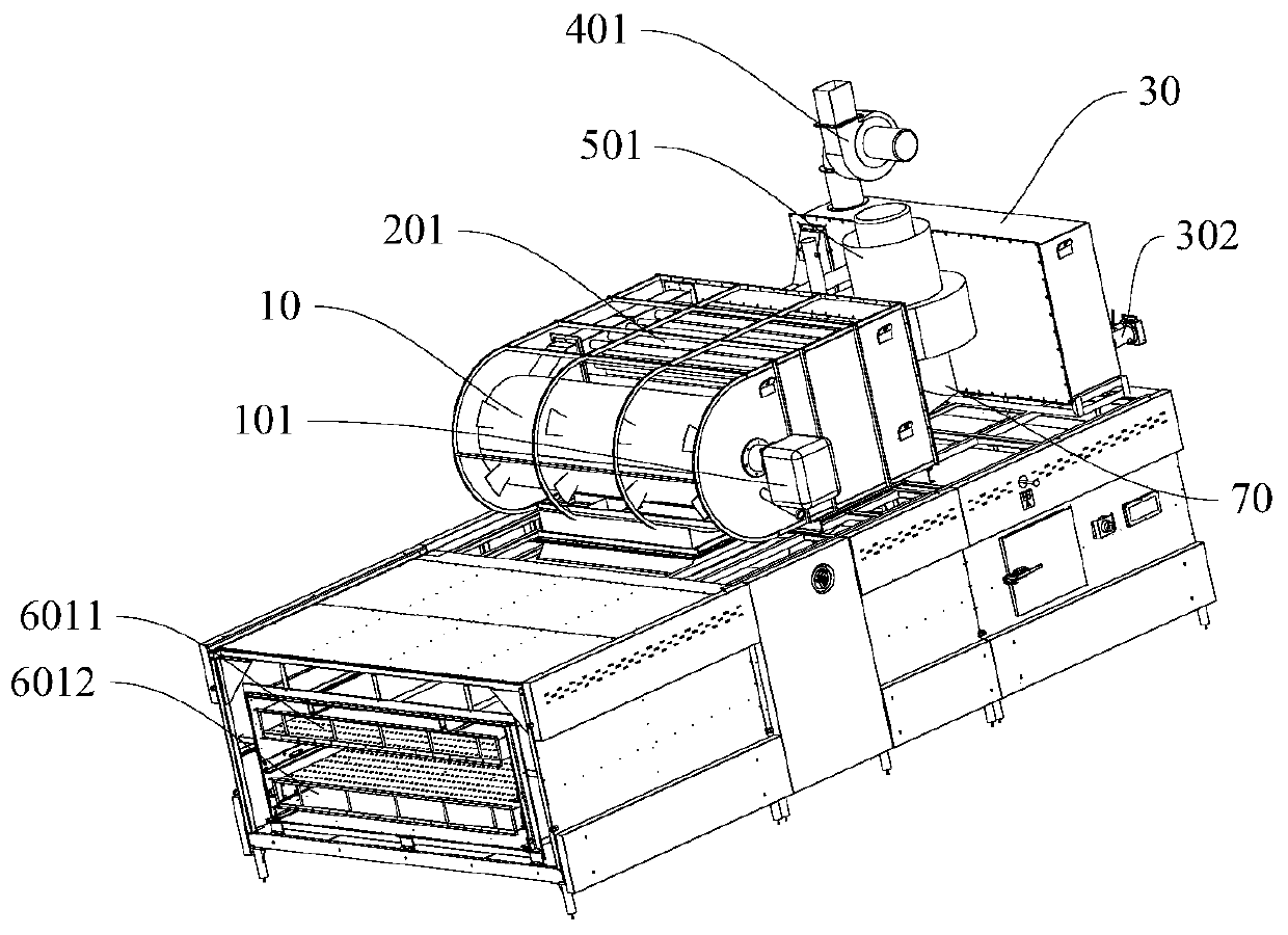
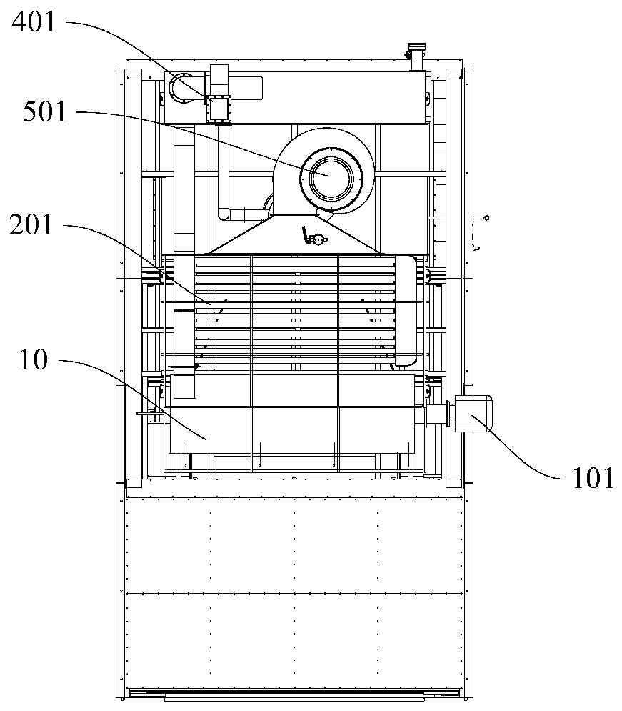
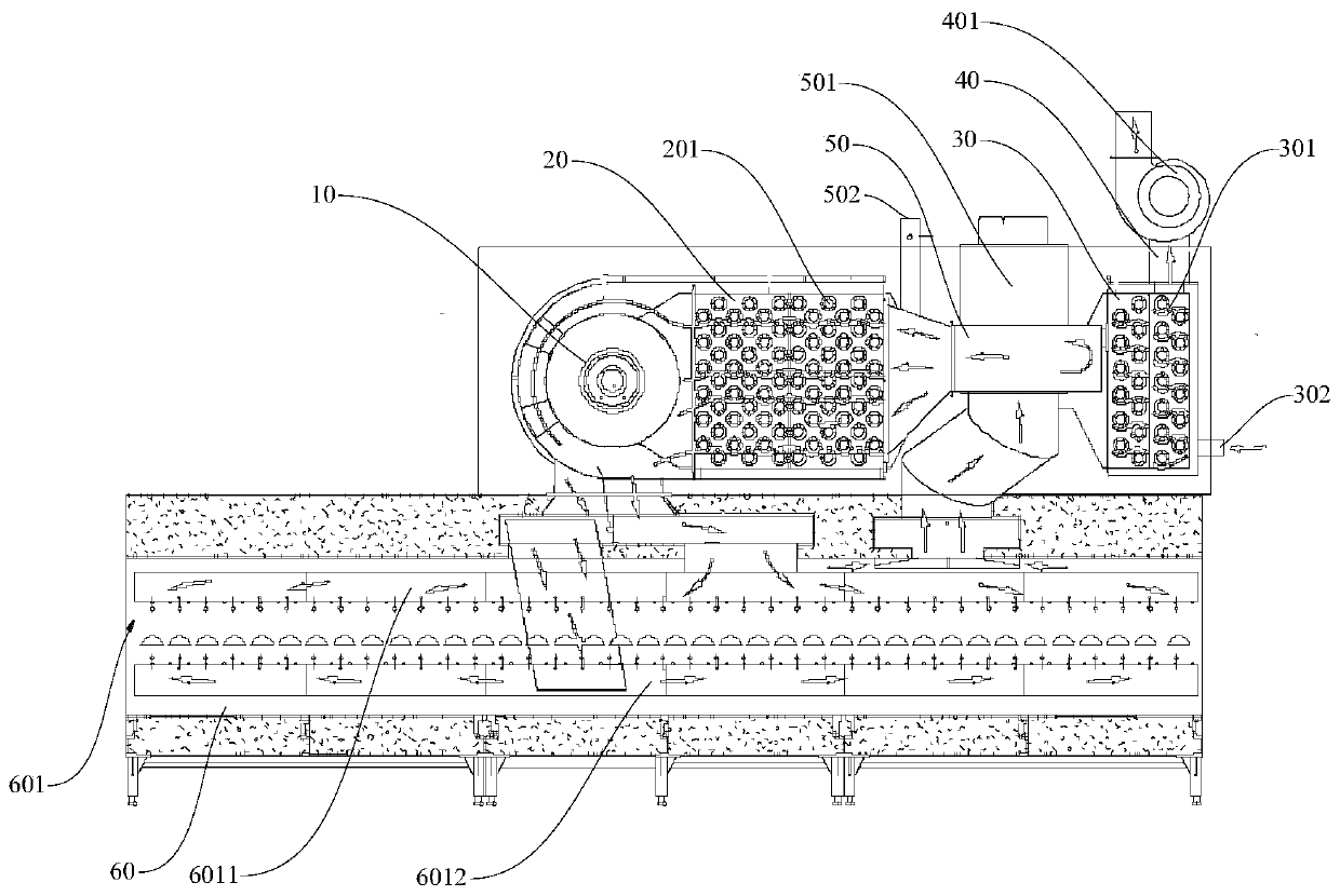
[0036] Such as Figure 1-5 A kind of secondary heat exchange type tunnel furnace shown, the combustion chamber 10 accommodates the air to be heated;

[0037] The burner 101 communicates with the combustion chamber 10, and the burner 101 is suitable for heating the air to be heated in the combustion chamber 10;

[0038] The first heat exchange chamber 20, the first heat exchange chamber 20 is equipped with a first heat exchange pipe 201 communicating with the combustion chamber 10, the first heat exchange pipe 201 is suitable for heating the air in the first heat exchange chamber 20;

[0039] The second heat exchange chamber 30, the second heat...


PUM


Abstract

The invention discloses a secondary heat exchange type tunnel furnace. The tunnel furnace comprises a combustion chamber, a burner, a first heat exchange chamber, a second heat exchange chamber and anexhaust pipe, wherein the combustion chamber contains to-be-heated air; the burner is communicated with the combustion chamber; the burner is suitable for heating the to-be-heated air in the combustion chamber; the first heat exchange chamber is internally provided with a first heat exchange tube communicated with the combustion chamber, and the first heat exchange tube is suitable for heating air in the first heat exchange chamber; a second heat exchange tube communicated with the first heat exchange tube is arranged in the second heat exchange chamber; the second heat exchange tube is suitable for heating air in the second heat exchange chamber; the exhaust pipe is communicated with the second heat exchange tube so that air flow heated by the combustion chamber can be discharged after passing through the first heat exchange tube and the second heat exchange tube. The secondary heat exchange type tunnel furnace is high in fuel utilization rage, and can prevent combustion waste gas from making direct contact with food and contaminating the food.

Description

technical field [0001] The invention relates to the technical field of tunnel furnaces, in particular to a secondary heat exchange tunnel furnace. Background technique [0002] Tunnel oven (food processing category) is a tunnel-type mechanical equipment that completes food baking through heat conduction, convection, and radiation. The oven body is generally very long, with a minimum of 6 meters and a length of 60 to 80 meters. The baking chamber is a long and narrow tunnel with a width of generally 80cm to 140cm. There is a continuously operating conveyor system inside the tunnel. When the food is baked, the relative movement between the food through the conveying chain plate, steel belt or mesh belt and the electric heating element or the direct-fired combustion rod occurs. Thereby completing the work of uniform baking and conveying. According to whether the flame enters the tunnel, the tunnel furnace is divided into flame tunnel furnace, flame insulation tunnel furnace...

Claims


Application Information

Patent Timeline
IPC IPC(8): A21B1/33A21B3/00F24H3/08F24H9/00
CPCA21B1/33A21B3/00F24H3/08F24H9/0052
Inventor 付文兵廖泽民李承平张书光
Owner GUANGZHOU FUYA MACHINERY
Features
  • R&D
  • Intellectual Property
  • Life Sciences
  • Materials
  • Tech Scout
  • Unparalleled Data Quality
  • Higher Quality Content
  • 60% Fewer Hallucinations
Learn More