
Ultrasonic scraping and shoveling processing device and vibration unit thereof

A technology of a processing device and a vibration unit, which is applied in the field of chipping processing devices, can solve the problems of difficult cultivation of talents, time-consuming, and bulky semi-automatic chipping machines

Inactive Publication Date: 2019-11-15
SHENZHEN TELLUS WEI TECH CO LTD
View PDF1 Cites 0 Cited by
  • Summary
  • Abstract
  • Description
  • Claims
  • Application Information

AI Technical Summary

Problems solved by technology

[0004] However, although the aforementioned manual shoveling or semi-automatic shoveling methods can produce pits on the workpiece, there are existing manual shoveling methods, which need to be carried out with a person holding a shoveling knife or a shoveling machine. , it is necessary to manually adjust the position, depth, size, etc. of the shoveling. It needs to rely on long-term experience accumulation, and is affected by the product and processing environment, so it is necessary to bend over for a long time It is processed with half-squatting, so the operation posture is quite uncomfortable. The manual shoveling technique is not only difficult to learn, but also laborious and time-consuming, which makes it difficult to develop talents
However, the manually clamped semi-automatic shoveling machine itself is quite heavy and requires good technology to operate, and needs to be improved.

Method used


Image

  • Ultrasonic scraping and shoveling processing device and vibration unit thereof
  • Ultrasonic scraping and shoveling processing device and vibration unit thereof
  • Ultrasonic scraping and shoveling processing device and vibration unit thereof

Examples


Embodiment Construction

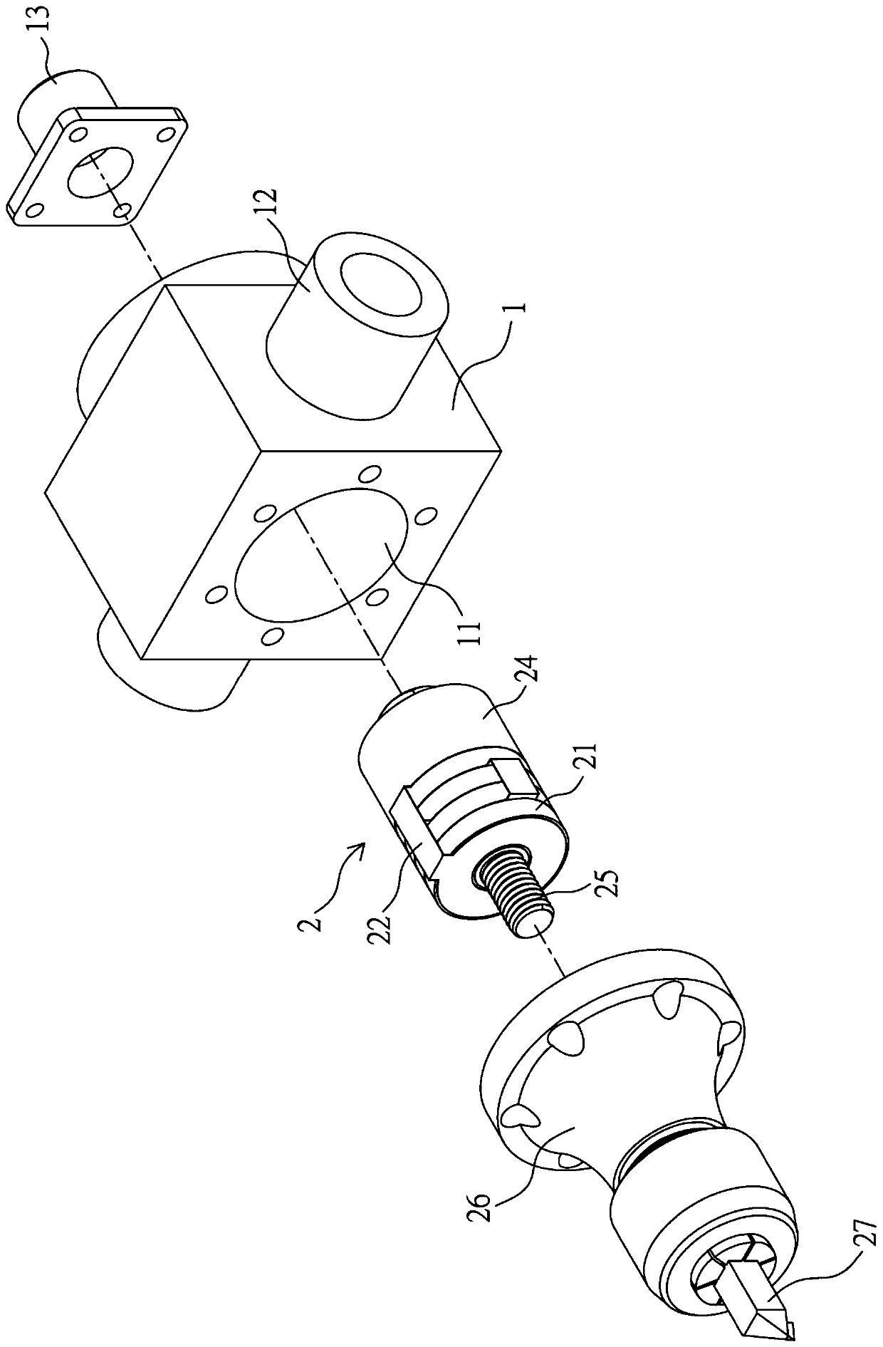
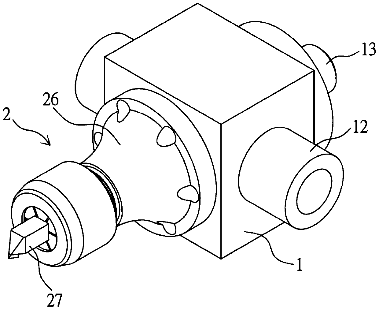
[0044] Figure 2 to Figure 4 As shown, the ultrasonic scraping processing device provided by the present invention includes a housing 1 and a vibration unit 2 .

[0045] The front of the housing 1 has an accommodating space 11 for the vibration unit 2 in the axial direction, and a connecting mechanism 12 is provided on at least one opposite side wall, such as figure 2 As shown, the connection mechanism 12 is an annular cylinder, but it is not limited thereto. In another embodiment, the pair of connection mechanisms 12 is a circular hole. Wherein the pair of connecting mechanisms 12 is provided for connecting and installing on a robot arm or a multi-axis processing machine (shown in image 3 ), so the ultrasonic scraping processing device is connected to the robot arm or the multi-axis processing machine through the connection mechanism 12, and moves with the robot arm or the multi-axis processing machine to perform scraping cutting operations.

[0046] In order to provide D...


PUM


Abstract

The invention provides an ultrasonic scraping and shoveling processing device. The ultrasonic scraping and shoveling processing device comprises a shell and a vibration unit, wherein an accommodatingspace is arranged on the front portion of the shell in the axial direction of the shell, and an electric connector is connected on the appropriate position; the vibration unit is arranged in the accommodating space and comprises a plurality of piezoelectric pieces and a conductive piece group with at least one first conductive piece and at least one second conductive piece; the piezoelectric pieces are formed into a parallel configuration by using the conductive piece group, and the piezoelectric pieces are adjacently connected with a telescopic piece; a connecting piece penetrates through thetelescopic piece and the piezoelectric pieces to be connected to an amplitude rod for installing a cutter; the electric connector is electrically connected with the at least one first conductive piece and the at least one second conductive piece; and a pair of grooves are oppositely arranged at the upper part or the lower part of the adjacent surface of the two adjacent piezoelectric pieces of the same pole, so that the piezoelectric pieces simultaneously form axial high-frequency vibration under the action of high-frequency voltage provided by the electric connector and are deformed by the existence of the grooves to generate radial deflection vibration to form an elliptical action path in the counterclockwise or clockwise direction.

Description

【Technical field】 [0001] The invention relates to a scraping processing device, in particular to an ultrasonic scraping processing device and a vibration unit thereof. 【Background technique】 [0002] According to the conventional scraping process, the main method is to manually scrape the workpiece, which can be divided into two categories: manual scraping and manual semi-automatic scraping. Among them, the manual scraping method is mainly two major scraping methods, one The waist shovel method is mainly used to hold the shovel knife handle against the waist, and use the half-squat to stand up and move forward to make the shovel knife scrape on the workpiece; the second is the arm shovel method, which is to shovel the knife The handle of the knife rests on the arm, and the spade knife is scraped on the workpiece by using the momentary force. [0003] The manual semi-automatic shoveling is to put half of the automatic shoveling machine on the shoulder, start the motor to mak...

Claims


Application Information

Patent Timeline
IPC IPC(8): B23P17/02
CPCB23P17/02
Inventor 李慧玲李武
Owner SHENZHEN TELLUS WEI TECH CO LTD
Features
  • Generate Ideas
  • Intellectual Property
  • Life Sciences
  • Materials
  • Tech Scout
  • Unparalleled Data Quality
  • Higher Quality Content
  • 60% Fewer Hallucinations
Learn More