
Reverse thrust centering and supporting device with adjustable length

A technology of support device and front support, which is applied to the power plant on the aircraft, the arrangement/installation of the power device, and the assembly of the aircraft, etc. It can solve the problems of imperfect function, insufficient installation compensation, and the inability of the thrust reverser to buckle, and achieve an increase in the The effect of horizontal limit function, reducing workload and improving reliability

Active Publication Date: 2019-11-15
AECC SHENYANG ENGINE RES INST
View PDF7 Cites 0 Cited by
  • Summary
  • Abstract
  • Description
  • Claims
  • Application Information

AI Technical Summary

Problems solved by technology

[0005] 2. The function is not perfect
It is impossible to visually check the state of the support rod when it is in contact with the work. In order to ensure normal use, the support rod and the support seat should have a clearance fit, otherwise the thrust reverser cannot be buckled, or the support rod is subjected to additional loads
Whether it is leaving a gap or additionally compressing the struts, it has the defect of not fully functioning
[0006] 3. Insufficient installation compensation
Therefore, this structure cannot satisfy the 100% success of the first assembly
Not suitable for rapid assembly of aero-engines or confined areas inside aircraft

Method used


Image

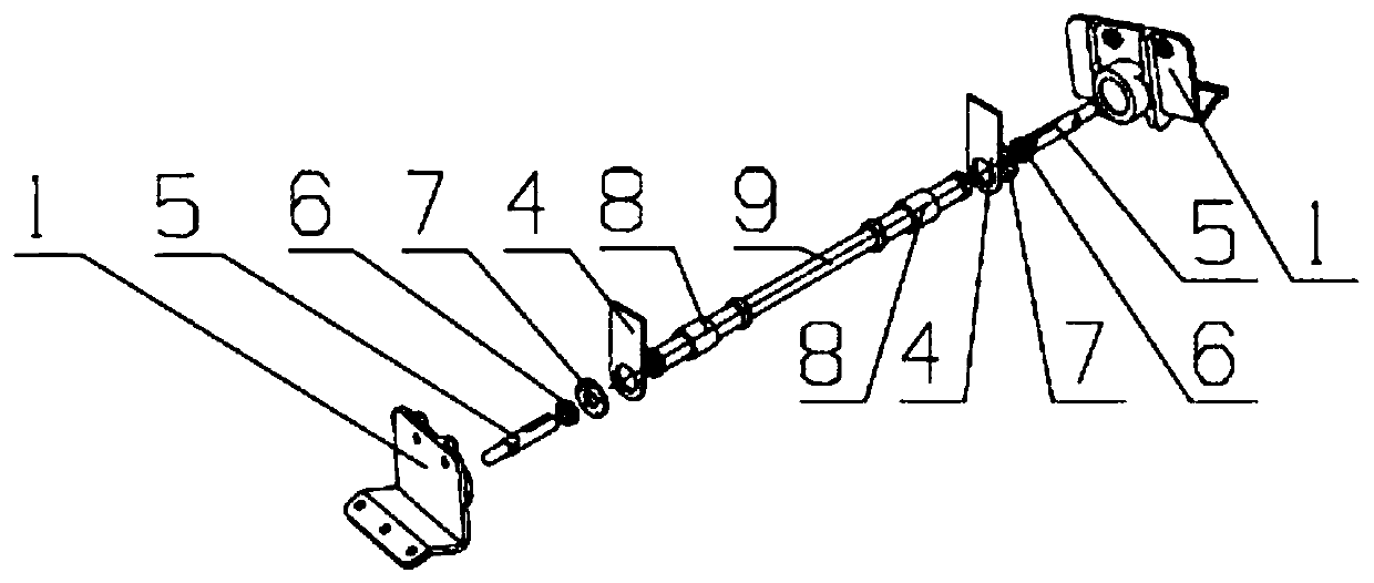
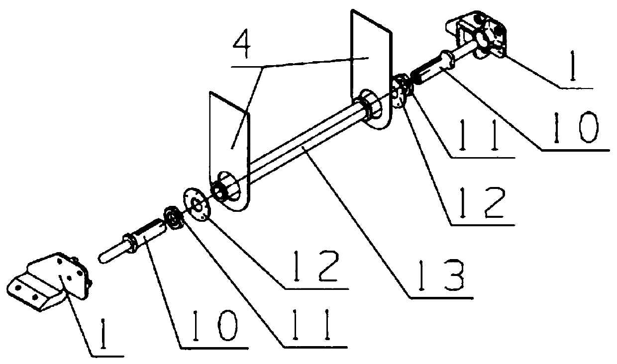
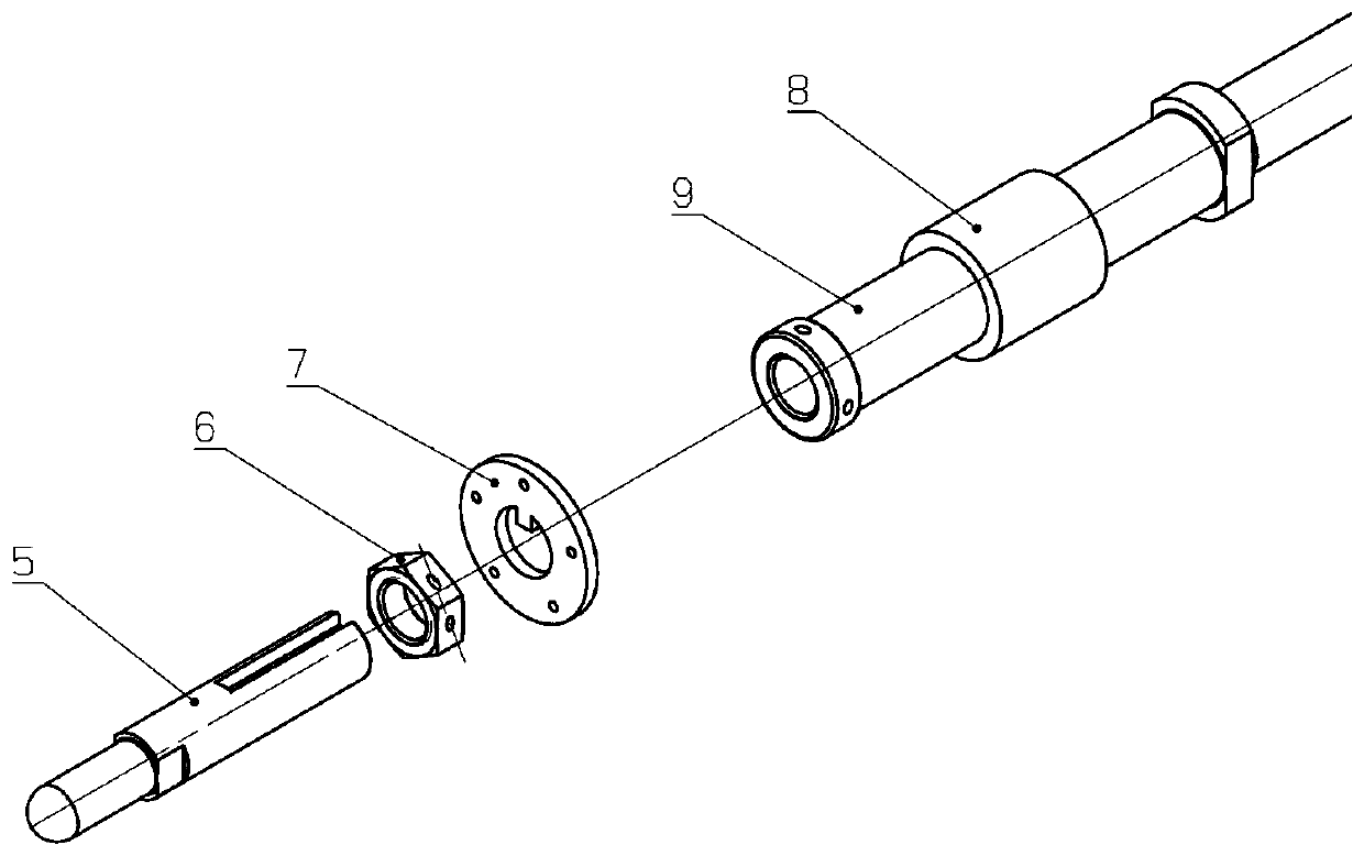
  • Reverse thrust centering and supporting device with adjustable length
  • Reverse thrust centering and supporting device with adjustable length
  • Reverse thrust centering and supporting device with adjustable length

Examples


Embodiment Construction

[0031] In order to make the objectives, technical solutions and advantages of the implementation of the application clearer, the technical solutions in the implementation modes of the application will be described in more detail below with reference to the drawings in the implementation modes of the application. In the drawings, the same or similar reference numerals denote the same or similar elements or elements having the same or similar functions throughout. The described embodiments are some, but not all, embodiments of the present application. The embodiments described below by referring to the figures are exemplary and are intended to explain the present application, and should not be construed as limiting the present application. Based on the implementation manners in this application, all other implementation manners obtained by persons of ordinary skill in the art without creative efforts fall within the scope of protection of this application. Embodiments of the pr...


PUM


Abstract

The invention belongs to the technical field of engine assembly design, and relates to a reverse thrust centering and supporting device with adjustable length. The device includes a front supporting rod assembly supported on thrust reversers located at both ends of a pylon, the front support rod assembly includes a front supporting rod adjusting joint, a locking nut, a front supporting rod limiting locking piece and a front supporting rod, the front supporting rod is of a cylindrical structure, internal threads are arranged at both ends of the front supporting rods, a ball head structure is arranged at one end of the front supporting rod adjusting joint, an external thread is arranged at the other end of the front supporting rod adjusting joint, a strip groove extending axially inward fromthe end part is formed in the end with the external thread, the front supporting rod limiting locking piece is provided with an outer ring and an inwardly extending protrusion, after the locking nutis assembled to the front supporting rod, limiting is performed by the front supporting rod limiting locking piece, and the front supporting rod adjusting joint is connected into a front supporting rod barrel in a threaded mode. The reverse thrust centering and supporting device is adjustable in length and can meet the use of different batches of thrust reversers of a same installation interface.

Description

technical field [0001] The application belongs to the technical field of engine assembly design, and in particular relates to an adjustable length reverse thrust centering support device. Background technique [0002] The thrust reverser is hinged on the pylon through two installation lifting points on the upper guide rail beam, and the front section is fastened to the outer ring of the engine intermediate casing and the nacelle connector through the inner and outer buckles. The upper isolation plate, the inner wall, and the rear end of the lower isolation plate of the thrust reverser are all in a cantilever state, and their rigidity is relatively weak. During the working process of the thrust reverser, the airflow of the outer culvert channel produces loads on the upper isolation plate, the inner wall and the lower isolation plate, and the load will deform the upper isolation plate inward. [0003] In the prior art, an independent hollow support rod is used for support to ...

Claims


Application Information

Patent Timeline
IPC IPC(8): B64F5/10B64D27/26
CPCB64F5/10B64D27/40Y02T50/40
Inventor 谭征岳刘洪波廉正彬田琦楠李盈建
Owner AECC SHENYANG ENGINE RES INST
Learn More