Powder spreading car
A technology for spreading vehicles and powder materials, which is applied in roads, road repairs, roads, etc., and can solve problems such as residual powder accumulation, uneven feeding in powder tanks, and interference with powder screw conveying, so as to achieve stable feeding and avoid downtime. The effect of poor material and reducing powder residue
- Summary
- Abstract
- Description
- Claims
- Application Information
AI Technical Summary
Problems solved by technology
Method used
Image
Examples
Embodiment 1
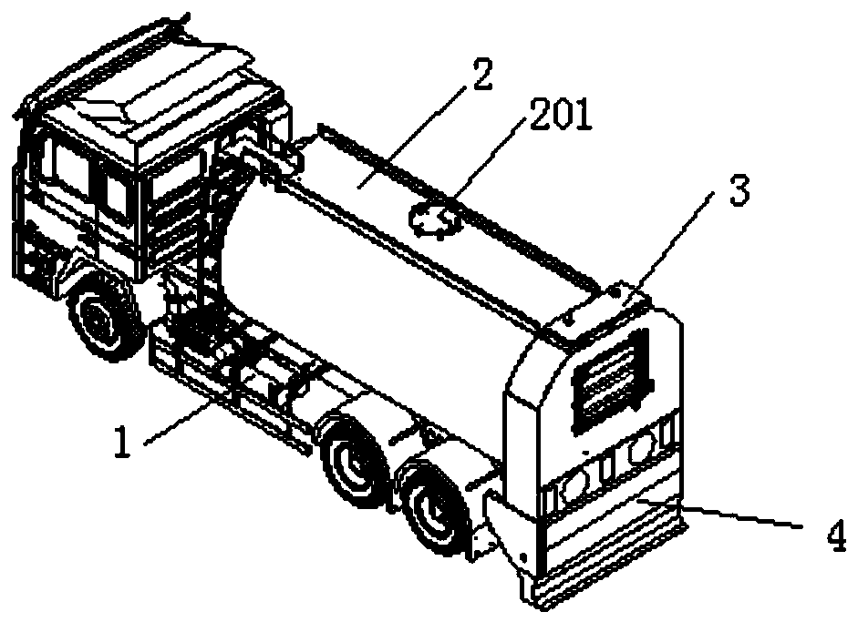
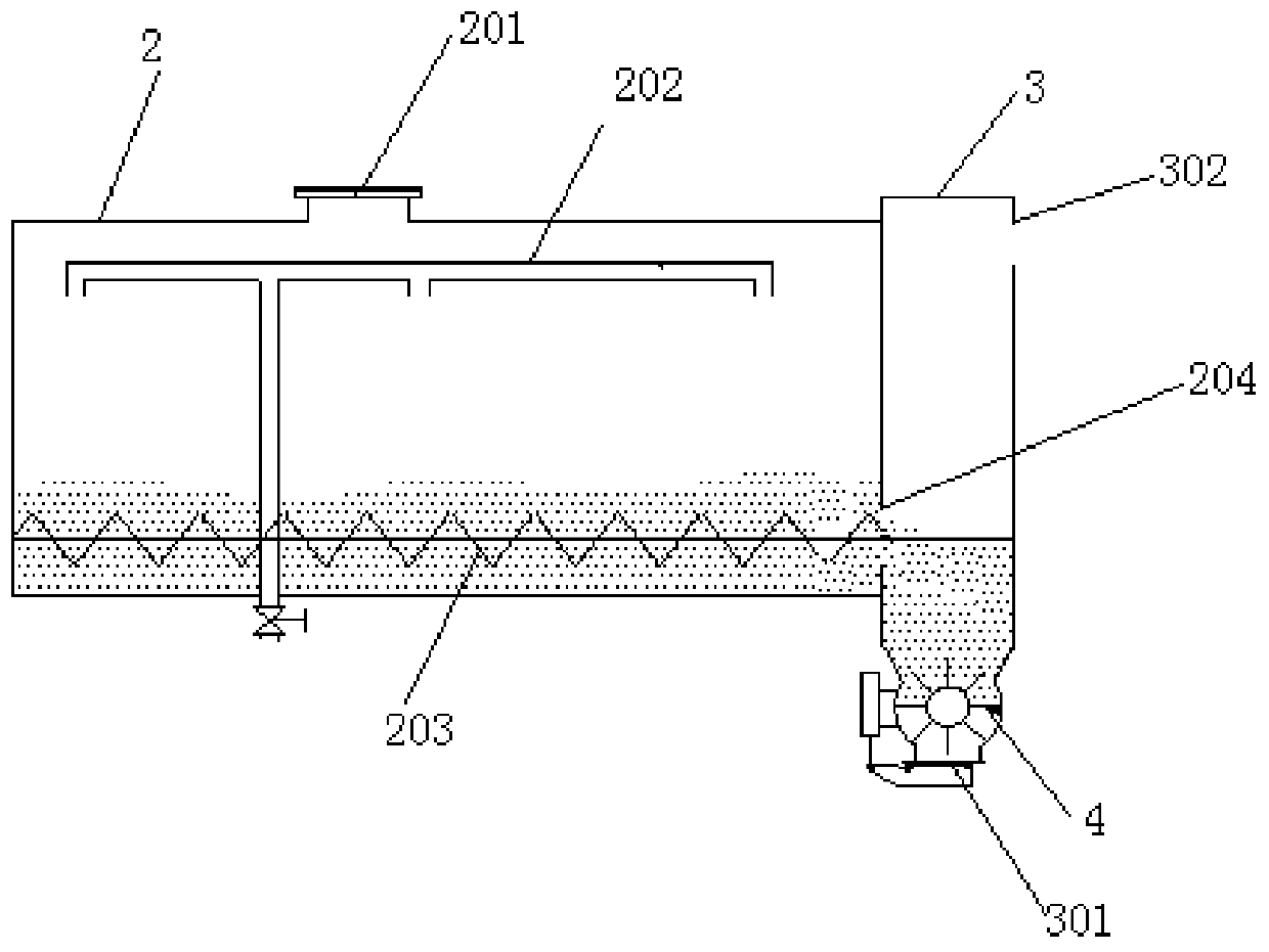
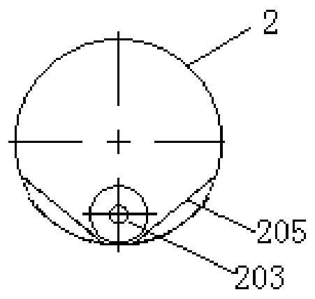
[0039] A powder spreading vehicle, comprising a vehicle body 1, a powder tank 2 fixedly installed on the vehicle body and a rear box body 3; the rear end of the powder tank 2 is provided with a screw feeding port 204, and the powder tank 2 passes through The screw feeding port is connected with the rear box 3; the cross section of the powder tank 2 is circular; the powder tank 2 is provided with a manhole 201, a feeding mechanism 202 is provided on the upper part, and a feeding screw rod 203 is provided at the bottom , the end of the feeding screw rod 203 is located at the screw feeding port 204; as image 3 , the feeding screw rod 203 is arranged at the bottom center of the powder material tank 2, and the both sides of the feeding screw rod 203 are provided with inclined slide plates 205, and there is a gap between the feeding screw rod 203 and the slide plate 205; the rear box body 3 The bottom is provided with a material door 301, and the upper part is provided with an exha...
Embodiment 2
[0041] A powder spreading vehicle, comprising a vehicle body 1, a powder tank 2 fixedly installed on the vehicle body and a rear box body 3; the rear end of the powder tank 2 is provided with a screw feeding port 204, and the powder tank 2 passes through The screw feeding port is connected with the rear box 3; the cross section of the powder tank 2 is circular; the powder tank 2 is provided with a manhole 201, the upper part is provided with a feeding mechanism 202, and the bottom is provided with two feeding screw rods 203, the end of the feeding screw rod 203 is located at the screw feeding port 204; as Figure 4 , the bottom of the powder tank 2 is provided with a herringbone plate 206, the feeding screw 203 is distributed on both sides of the herringbone plate 206, and there is a gap between the feeding screw 203 and the herringbone plate 206; the rear box The bottom of the body 3 is provided with a material door 301 , and the upper part is provided with an exhaust port 30...
Embodiment 3
[0043] A powder spreading vehicle, comprising a vehicle body 1, a powder tank 2 fixedly installed on the vehicle body and a rear box body 3; the rear end of the powder tank 2 is provided with a screw feeding port 204, and the powder tank 2 passes through The screw feeding port is connected with the rear box 3; the cross section of the powder tank 2 is oval; the powder tank 2 is provided with a manhole 201, the upper part is provided with a feeding mechanism 202, and the bottom is provided with three feeding screw rods 203 , the end of the feeding screw rod 203 is located at the screw feeding port 204; as Figure 5 , the bottom of the powder tank 2 is provided with two herringbone plates 206, the feeding screw 203 is distributed on both sides of the herringbone plate 206, and there is a gap between the feeding screw 203 and the herringbone plate 206; The bottom of the box body 3 is provided with a material door 301 , and the upper part is provided with an exhaust port 302 ; the...
PUM
 Abstract
Description
Claims
Application Information
 - R&D
- Intellectual Property
- Life Sciences
- Materials
- Tech Scout
- Unparalleled Data Quality
- Higher Quality Content
- 60% Fewer Hallucinations
Browse by: Latest US Patents, China's latest patents, Technical Efficacy Thesaurus, Application Domain, Technology Topic, Popular Technical Reports.
© 2025 PatSnap. All rights reserved.Legal|Privacy policy|Modern Slavery Act Transparency Statement|Sitemap|About US| Contact US: help@patsnap.com


