Steam turbine slim blade and moving blade assembly consisting of same

A technology of steam turbine and blade group, which is applied in the direction of supporting components of blades, machines/engines, mechanical equipment, etc., and can solve problems such as difficult installation of blades, restrictions on the production and application of steam turbines, and the inability of standard moving blades to be installed on the rotor through blade root slots, etc. Achieve the effects of improving flatness, overcoming difficulty in installation, and reducing air leakage in the stage

Pending Publication Date: 2019-11-15
CHINA CHANGJIANG ENERGY CORP GROUP
0 Cites 0 Cited by

AI-Extracted Technical Summary

Problems solved by technology

For conventional models, the moving blades are installed on the rotor in a ring shape; but for high-speed models, there are many types of moving blades, but there will be a standard moving blade that cannot pass through the blade root slot during assembly Installed on the rotor, the structure of the standard moving blade is as follows figure 1 As shown, the side of the blade root o...

Method used

The steam turbine slimming blade that the embodiment of the present invention provides, the lower end of airfoil portion is fixedly connected with blade root portion upper end; Shroud is fixed on blade airfoil upper end, and shroud upper end is provided with boss at intervals, boss and steam seal tooth phase Cooperate. Compared with traditional standard moving blades, in the trimming blade of steam turbine provided by the present invention, the trapezoid on the side of the blade root determines the second waistline through the upper bottom, lower bottom and first waistline, and the first sideline and the second waistline of the blade body side The first waistline is connected, the second sideline on the side of the blade body is connected to the second waistline, and the second sideline is on the extension line of the second waistline. The protruding structure on the side of the standard moving blade is cut off, and the two sides of the blade body are respectively set on the extension line of the two sides of the blade root, which improves the flatness of the blade body, thereby overcoming the traditional standard The technical problem of difficult installation caused by the protrusion on the moving blade. In addition, in the trimmed blade of the steam turbine provided by the invention, the boss cooperates with the seal teeth to form a radial seal, which can reduce air leakage in the stage.
[0019] Referring t...

Abstract

The invention relates to a steam turbine slim blade. The steam turbine slim blade comprises a blade body part, a blade root part, a surrounding belt and bosses, wherein the lower end of the blade bodypart is fixedly connected with the upper end of the blade root part, the surrounding belt is fixed at the upper end of the blade body part, the bosses are arranged at the upper end of the surroundingbelt at intervals, and the bosses are matched with steam sealing teeth; the blade root part is arranged to be a trapezoid shape with the length of an upper bottom longer than that of a lower bottom,a second waist line is determined through the upper bottom, the lower bottom and a first waist line of the trapezoid where the side face of the blade root part is located, a first side line of the side face of the blade body part is connected with the first waist line, a second side line of the side face of the blade body part is connected with the second waist line, and the second side line is located on an extension line of the second waist line. The invention further provides a moving blade assembly of a steam turbine. At least one steam turbine slim blade is arranged on the moving blade assembly of the steam turbine. According to the steam turbine slim blade, a bulging structure arranged on the upper side face of a standard moving blade is cut off, the flatness of the blade body part is improved, and the technical problem that a traditional standard moving blade is difficult to install due to the bulge on the traditional standard moving blade is solved.

Application Domain

Blade accessoriesLeakage prevention +1

Technology Topic

EngineeringSteam turbine

Image

  • Steam turbine slim blade and moving blade assembly consisting of same
  • Steam turbine slim blade and moving blade assembly consisting of same
  • Steam turbine slim blade and moving blade assembly consisting of same

Examples

  • Experimental program(1)

Example Embodiment

[0017] Aiming at the technical problem that the moving blades are difficult to install in the prior art, the present invention provides a steam turbine self-cultivating blade and a moving blade group formed by it.
[0018] The following describes the technical solutions in the embodiments of the present invention clearly and completely with reference to the accompanying drawings in the embodiments of the present invention. Obviously, the described embodiments are only a part of the embodiments of the present invention, rather than all the embodiments. Based on the embodiments of the present invention, all other embodiments obtained by those of ordinary skill in the art without creative work fall within the protection scope of the present invention.
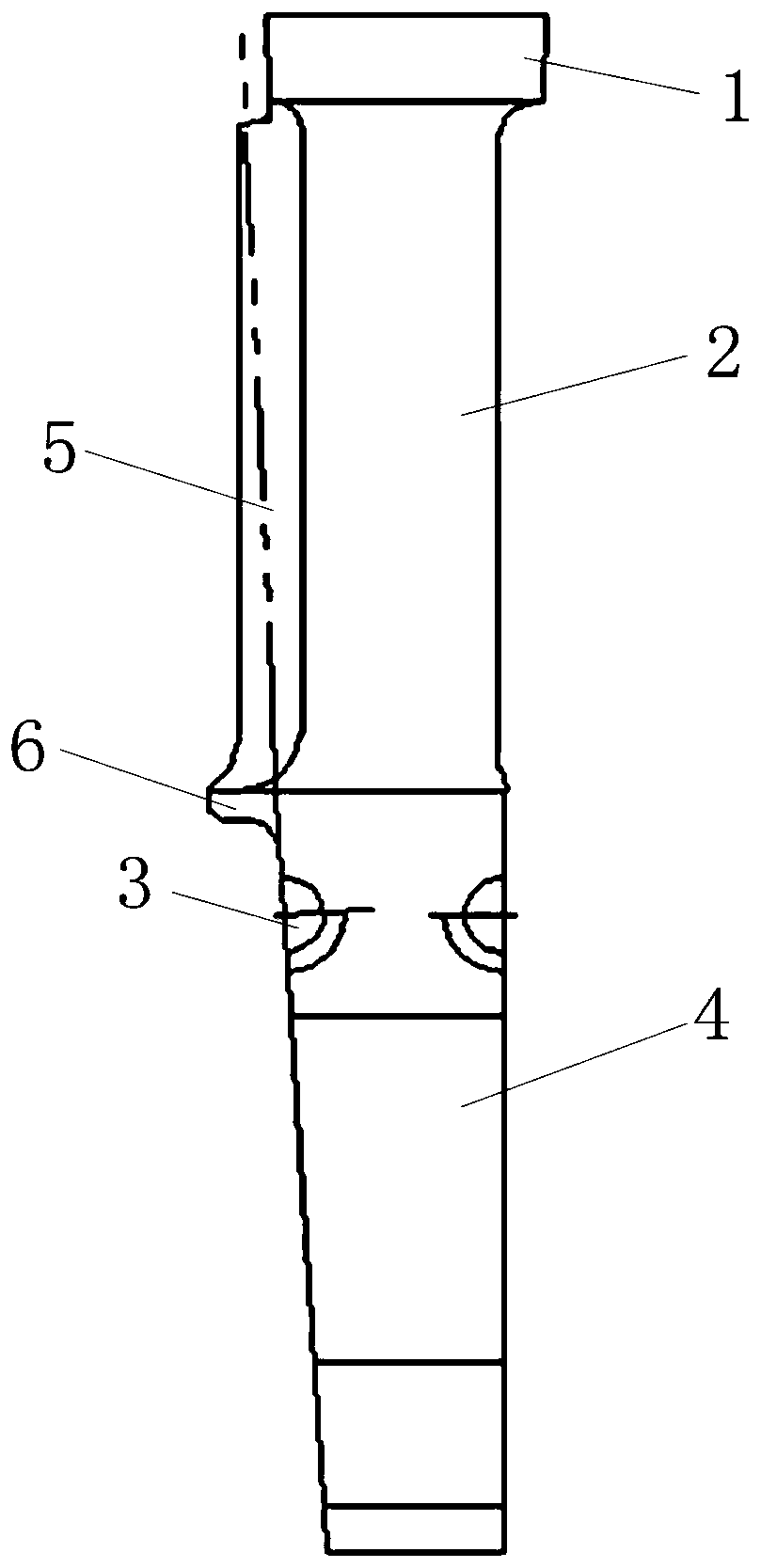
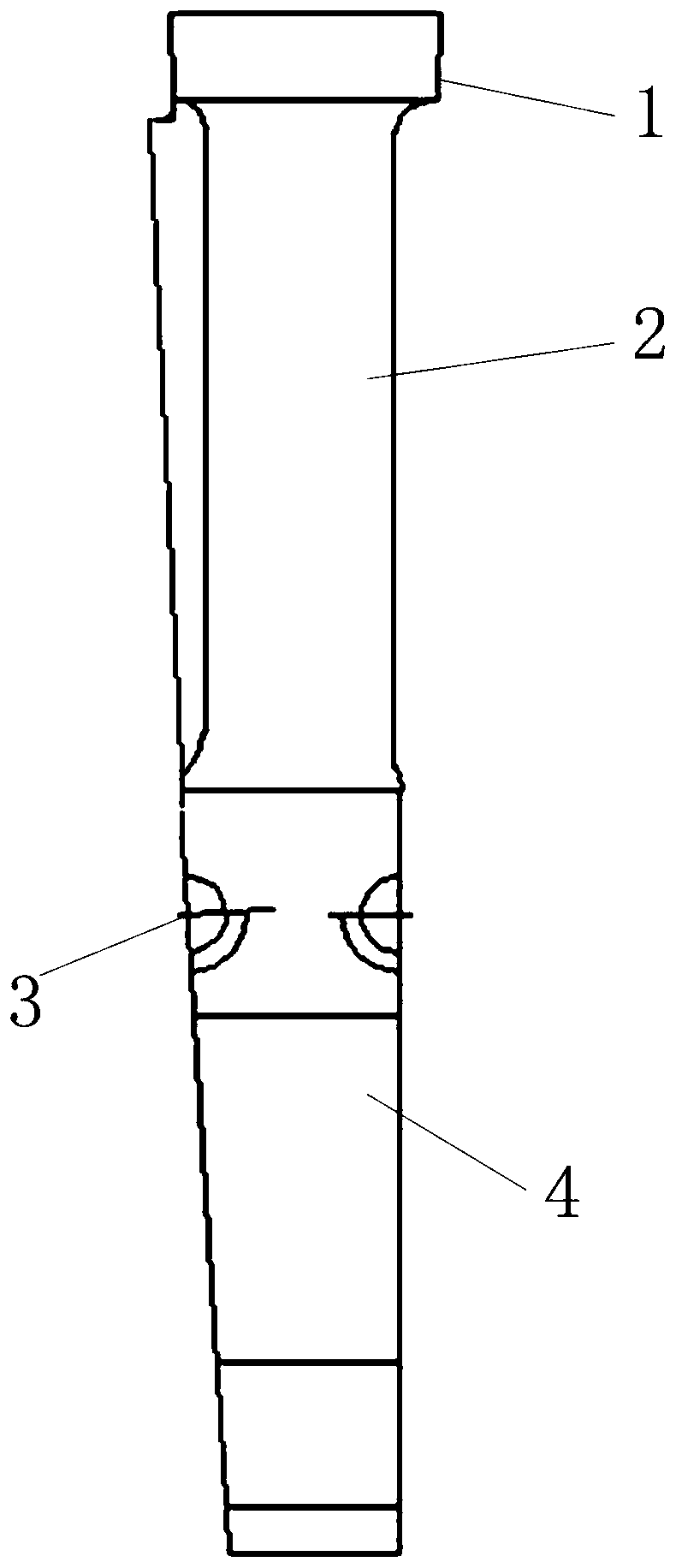
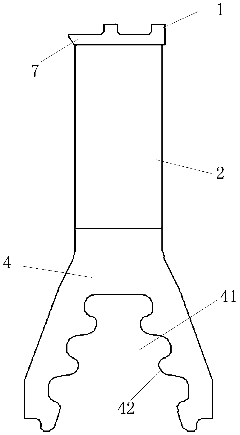
[0019] See Figure 1-Figure 3 , The embodiment of the present invention provides a steam turbine self-cultivating blade, including: a blade body 2, a blade root 4, a shroud 7 and a boss 1. Among them: the lower end of the blade body 2 is fixedly connected with the upper end of the blade root 4; the shroud 7 is fixed at the upper end of the blade body 2, and the upper end of the shroud 7 is provided with bosses 1 at intervals, and the bosses 1 are matched with the sealing teeth. In practical applications, the blade body 2, blade root 4, shroud 7 and boss 1 are integrally manufactured, and they are all made of stainless steel. The trapezoid on the side of the leaf root 2 determines the second waist line by the upper bottom, lower bottom and the first waist line. The first side line on the side of the leaf body 2 meets the first waist line, and the second side of the leaf body 2 The side line is connected with the second waist line, and the second side line is on the extension line 5 of the second waist line, thereby forming a self-cultivating blade with a trapezoidal structure on the side of the blade body 2. The side surface of the blade root 4 and the side surface of the blade body 2 are smooth and transitional, which facilitates the installation of the slim blade. It should be noted that the trapezoidal structure described in the embodiment of the present invention has a trapezoidal shape as a whole, and corresponding detailed positions, such as the connection of two sides, can be smoothly transitioned at a certain angle.
[0020] In the embodiments of the present invention, see image 3 , Leaf root 4 is fungus-type leaf root. A root wheel groove 41 is provided on the blade root 4, the root wheel groove 41 is downwardly open and the front and rear ends of the root wheel groove 41 are open, that is, the root wheel groove 41 is a groove that penetrates through the front and rear ends and opens on the ground. The left and right groove surfaces of the root groove 41 are respectively provided with flange protrusions 42. The front and back of the root body are respectively provided with balance grooves, and the balance grooves are arranged on the root body above the root wheel groove 41 and/or the balance grooves are arranged on the corresponding root body in the upper part of the root wheel groove 41. The blade root 4 is provided with a pin hole 3. The pin hole 3 is used to pass through the pin to fix the adjacent moving blade, and to be tightly connected with the adjacent moving blade; the shape of the pin hole 3 matches the shape of the pin, in this embodiment The pin hole 3 is set to be circular.
[0021] In addition, the embodiment of the present invention also provides a steam turbine rotor blade assembly, and the steam turbine rotor blade assembly is provided with a steam turbine self-cultivating blade. When installing the moving blades of the steam turbine moving blade set provided by the present invention, the moving blades of various specifications are first installed on the rotor, and finally the slim blades provided in this embodiment are installed. The side of the blade body 2 of the slim blades is set in an isosceles trapezoid. The shape can be easily inserted into the corresponding installation position.
[0022] The steam turbine slim blade provided by the embodiment of the present invention has at least the following beneficial effects or advantages:
[0023] In the steam turbine slimming blade provided by the embodiment of the present invention, the lower end of the blade body is fixedly connected with the upper end of the blade root; the shroud is fixed on the upper end of the blade, and the upper end of the shroud is provided with bosses at intervals, and the bosses are matched with the steam seal teeth. Compared with the traditional standard moving blades, the steam turbine slim blade provided by the present invention has a trapezoid on the side of the blade root. The second waist line is determined by the upper bottom, the lower bottom and the first waist line. A waist line is connected, the second side line on the side of the blade body is connected with the second waist line, and the second side line is on the extension line of the second waist line. The raised structure provided on the upper side of the standard moving blade is cut off, and the two sides of the blade body are respectively set on the extension lines of the two sides of the blade root, which improves the flatness of the blade body and can overcome the traditional standard Technical problems that are difficult to install caused by the protrusions on the moving blades. In addition, in the steam turbine self-cultivating blade provided by the present invention, the bosses and the steam seal teeth cooperate to form a radial steam seal, which can reduce air leakage in the stage.
[0024] The above descriptions are only preferred embodiments of the present invention and are not intended to limit the present invention. Any modification, equivalent replacement, improvement, etc. made within the spirit and principle of the present invention shall be included in the protection of the present invention. Within range.

PUM

no PUM

Description & Claims & Application Information

We can also present the details of the Description, Claims and Application information to help users get a comprehensive understanding of the technical details of the patent, such as background art, summary of invention, brief description of drawings, description of embodiments, and other original content. On the other hand, users can also determine the specific scope of protection of the technology through the list of claims; as well as understand the changes in the life cycle of the technology with the presentation of the patent timeline. Login to view more.

Similar technology patents

Thermal spraying processing method for carbon anode used for preparing fluorine

Owner:HUAHE NEW TECH DEV COMPANY RES INST OF PHYSICAL & CHEM ENG OF NUCLEAR IND

Semiconductor structure and formation method thereof

ActiveCN107039275AExcellent electrical performanceImprove flatness
Owner:SEMICON MFG INT (SHANGHAI) CORP +1

Novel seamless spliced plate

Owner:湖南托斯卡纳电气有限公司

Organic polymer film for OLED (organic light emitting diode) device film packaging and application of organic polymer film

InactiveCN110317425AImprove flatnessreduce mechanical damage
Owner:ZHEJIANG HUADISPLAY OPTOELECTRONICS CO LTD

Classification and recommendation of technical efficacy words

Why Eureka
Try Eureka