Electromagnetic excitation response signal mutual inductance device, detection device and detection method

A technology that responds to signals and electromagnetic excitation, applied in the field of physical detection, can solve the problems of discounted excitation strength, weakened excitation signal, and limited exploration capabilities, etc., and achieves the effect of low production cost and wide application

Pending Publication Date: 2019-11-15
刘卫军
View PDF2 Cites 1 Cited by
  • Summary
  • Abstract
  • Description
  • Claims
  • Application Information

AI Technical Summary

Problems solved by technology

[0005] The patent document with the application number 201110424903.9 discloses the gradient measurement mode, the middle coil transmits, and the transmitting coil is a certain distance away from the surface of the measured medium, and the excitation strength of the primary field is discounted; in addition, due to geometrical constraints, the two receiving coils or sensors The geometric distance cannot be too large, and the amplitude of the obtained gradient signal will also be restricted, and there is no fundamental solution to the problem that the transmitting and receiving coils are close to the target surface at the same time.
[0006] The patent document with the application number 201410092714.X discloses the equivalent reverse magnetic flux measurement mode, and the two transmitting coils are fed with reverse currents. Obviously, the excitation signal of the primary field is greatly weakened, which limits the exploration capability and has no fundamental Solve the problem of sending and receiving coils close to the target surface at the same time

Method used


Image

  • Electromagnetic excitation response signal mutual inductance device, detection device and detection method
  • Electromagnetic excitation response signal mutual inductance device, detection device and detection method
  • Electromagnetic excitation response signal mutual inductance device, detection device and detection method

Examples


Embodiment 1

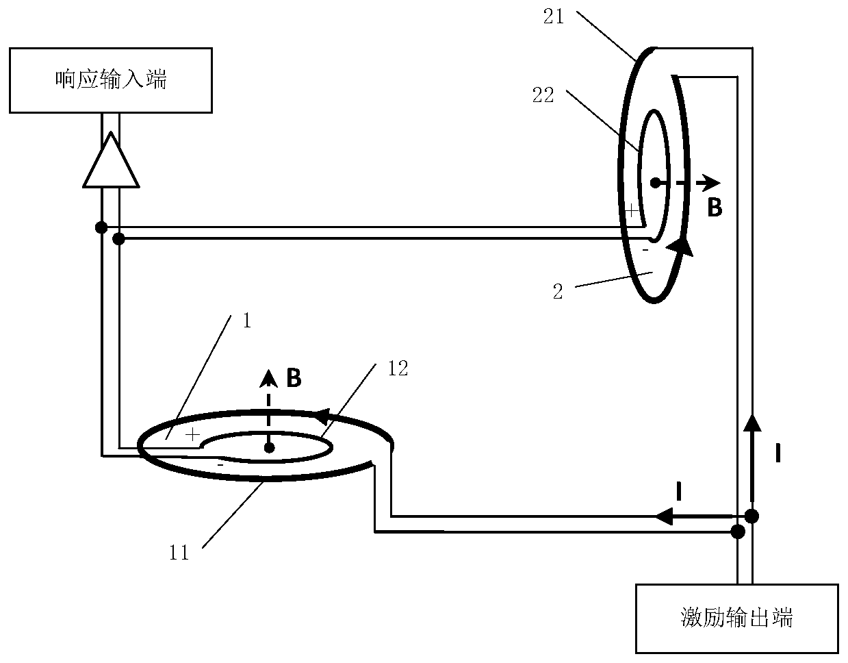
[0043] Please also refer to figure 1 , the present invention provides an electromagnetic excitation response signal mutual induction device, including a detector, a comparator installed at the geometric position of the detector;

[0044] The detector 1 includes a main excitation source 11 and a main receiving probe 12;

[0045] The comparator 2 includes a standby excitation source 21 and a standby receiving probe 22;

[0046] The main excitation source 11 is connected in parallel or in series with the standby excitation source 21; ensure that the current direction of the received excitation signal is the same;

[0047] The main receiving probe 12 and the standby receiving probe 22 are connected in anti-parallel or anti-series.

[0048] Specifically, in the mutual induction device provided by the present invention, the main function of the detector 1 is to perform point-by-point detection on the medium to be measured, and the main function of the comparator 2 is to filter out...

Embodiment 2

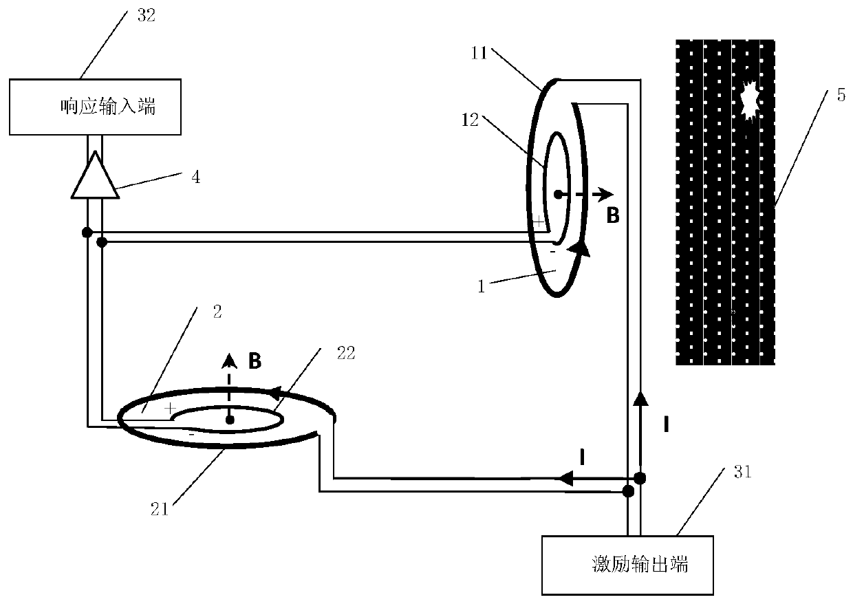
[0063] For details, please refer to figure 2 , the present invention also provides an electromagnetic excitation response signal detection device, using the mutual induction device in Embodiment 1, and also comprising an electromagnetic observer; the electromagnetic observer includes an excitation output terminal and a response input terminal;

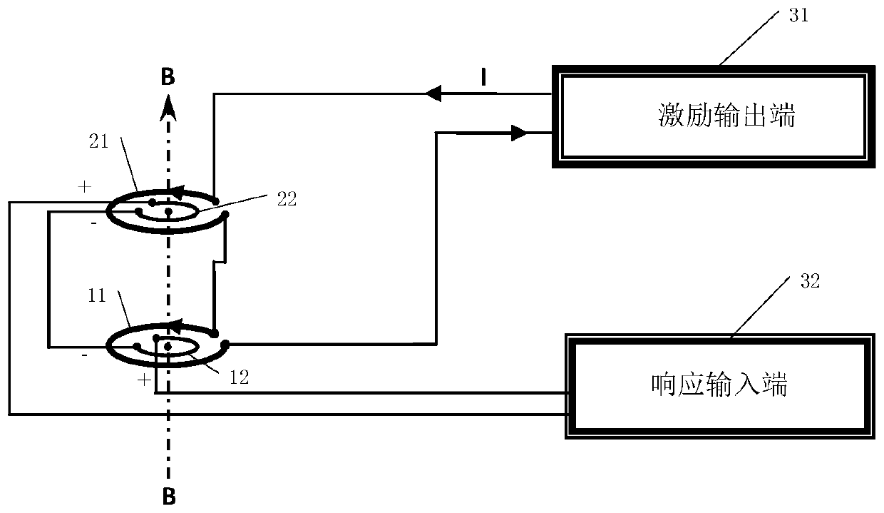
[0064] The main excitation source 11 and the standby excitation source 21 are connected in parallel / serial connection respectively with the excitation output terminal 31 of the electromagnetic observer;

[0065] The main receiving probe 12 and the standby receiving probe 22 are connected in antiparallel / reverse series, respectively, to the response input end 32 of the electromagnetic observer.

[0066] Specifically, the excitation output terminal 31 has two terminals, corresponding to the output and input of the electromagnetic excitation current; the response input terminal 32 has two terminals, respectively corresponding to the main...

Embodiment 3

[0075] Please also refer to figure 2 , the ring-shaped main excitation source 11 is wound with a wire with a diameter of 0.5 meters, a wire diameter of 2 square millimeters, and a number of turns of 10 turns, and the main receiving probe 12 is ring-wound with a wire with a diameter of 0.3 meters, a wire diameter of 1 square millimeter, and a number of turns of 100 turns , form the detector 1 with the main excitation source 11 and the main receiving probe 12 of the common center point and coplanar; The same received probe builds a comparator 2; the main excitation source 11 and the standby excitation source 21 are connected in parallel to form an excitation signal transmitting end, and the main receiving coil and the standby receiving coil are connected in reverse series to form an electromagnetic response signal Receiving end. The transient electromagnetic instrument is used as the electromagnetic observer.

[0076] After testing experiments, in free air, if the planes wher...


PUM


Abstract

The invention relates to an electromagnetic excitation response signal mutual inductance device, a detection device and a detection method. The electromagnetic excitation response signal mutual inductance device comprises a detector and a comparator arranged in a geometric position of the detector; the detector comprises a main excitation source and a main receiving probe; the comparator comprisesa standby excitation source and a standby receiving probe; the main excitation source and the standby excitation source are connected in parallel or in series; and the main receiving probe and the standby receiving probe are reversely connected in parallel or in series. Compared with the prior art, the electromagnetic excitation response signal mutual inductance device, the detection device and the detection method have the advantages that a signal comparator is used for following the detector in real time, a primary field signal caused by a signal magnetic field is reduced in an analog circuit, no matter what the excitation signal is, the primary field signal of the excitation signal can be completely inhibited, and the device is low in manufacturing cost.

Description

technical field [0001] The invention relates to the field of physical detection, in particular to an electromagnetic excitation response signal mutual induction device, a detection device and a detection method. Background technique [0002] Based on the principle of electromagnetic induction, the use of electromagnetic excitation response to realize non-destructive testing, flaw detection or geophysical exploration has many advantages such as no need to contact objects, simple equipment, high detection efficiency and low equipment cost. [0003] However, whether it is eddy current detection or transient electromagnetic method exploration in geophysical exploration, the launch system needs to launch the excitation electromagnetic field through the emission wire frame during implementation, and collect and record the electromagnetic response signal during or after the field excitation. This electromagnetic response signal includes both the mutual inductance signal of the tran...

Claims


Application Information

Patent Timeline
IPC IPC(8): G01V3/08G01V3/10G01V3/38
CPCG01V3/08G01V3/10G01V3/38
Inventor 刘卫军朱朴厚
Owner 刘卫军
Why Eureka
Try Eureka