
Method for calculating odd vein shunt ratio in semi-ventricular model based on geometric multi-scale model

A calculation method, azygos vein technology, applied in the direction of calculation, 3D modeling, image data processing, etc., can solve the problems of instrument error, patient discomfort, magnetic resonance operation, high medical cost of patients, etc., to achieve the effect of convenient change

Active Publication Date: 2019-11-15
BEIJING UNIV OF TECH
View PDF3 Cites 1 Cited by
  • Summary
  • Abstract
  • Description
  • Claims
  • Application Information

AI Technical Summary

Problems solved by technology

Although this method can quickly obtain the flow velocity of each blood vessel through imaging equipment, the instrument itself has certain errors; secondly, it costs a lot to patients, and some patients are not suitable for MRI operations

Method used


Image

  • Method for calculating odd vein shunt ratio in semi-ventricular model based on geometric multi-scale model
  • Method for calculating odd vein shunt ratio in semi-ventricular model based on geometric multi-scale model
  • Method for calculating odd vein shunt ratio in semi-ventricular model based on geometric multi-scale model

Examples


Embodiment 1

[0045] 1. Constructing a Half Ventricle Model

[0046] 1.1 Using gray threshold segmentation and region growing methods to process CT image data in Mimics, a semi-ventricular model with azygos vein inner diameter of 5 mm is preliminarily obtained, and the saving format is ".stl".

[0047] 1.2 Import the model obtained in step 1.1 into Freeform, use the force feedback device to modify the discontinuous and obvious mutation parts of the model, and export a smooth 3D model.

[0048] 1.3 Import the model obtained in step 1.2 into Geomagic, perform surface smoothing operations to simplify the model, and export the 3D model in ".igs" format.

[0049] 1.4 Import the model obtained in step 1.3 into SolidWorks, establish a datum plane at the exit / entrance, cut out the boundary to make the boundary of the 3D model smooth; convert the model in ".igs" format to ".x-t" that can be used for finite element calculations "data. Such as Figure 4 .

[0050] 2. Establish 0D centralized param...

example 1

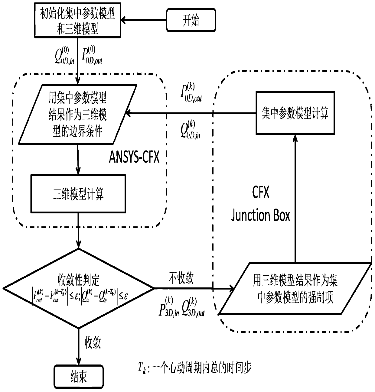
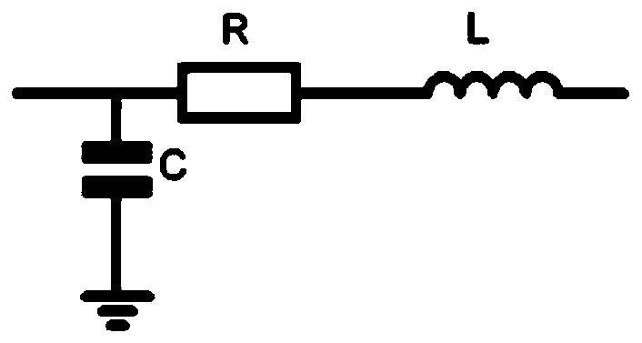
[0051] The 0D centralized parameter model established in Example 1 is as follows Figure 5 shown. A semi-ventricular model is expressed as a 3D model, and the peripheral circulation part connected to it is expressed as a 0D lumped parameter model, thus forming a 0D / 3D coupling model. The 0D / 3D coupling model established in Example 1 is as follows: Figure 6 shown.

[0052] 3. Geometric multi-scale finite element analysis

[0053] Debug parameter E of 0D lumped parameter model max ,E min , R, C and L, so that the waveform of the exit / entry boundary conforms to the physiological reality when the lung resistance is 2Wood, such as Figure 7 shown.

[0054] According to the parameters at this time, the 3D model in the format of ".x-t" is 0D / 3D coupled with the 0D centralized parameter model inlet and outlet boundary condition data: first, use the UserJunction Box Routine program block in ANSYS-CFX to complete the 0D / 3D model initialization; In the pre-processing of ANSYS-CFX,...


PUM


Abstract

The invention relates to a method for calculating an odd vein shunt ratio in a semi-ventricular model based on a geometric multi-scale model, and belongs to the field of hemodynamic numerical simulation. A 0D / 3D coupled geometric multi-scale model is used for carrying out hemodynamic finite element analysis to acquire the odd vein shunt ratio. A semi-ventricle model is represented by a 3D model, and a peripheral circulation part connected with the semi-ventricle model is represented by a 0D lumped parameter model, so that a 0D / 3D combined geometric multi-scale model is formed. Finite element analysis is applied to the 0D / 3D coupling model, and the hemodynamic condition of one semi-ventricular model under different pulmonary resistances is simulated. After calculation is completed, in ANSYS-CFX post-processing, the odd vein shunt ratio is calculated by defining an expression; and the wall shear stress of the odd vein can be extracted, and the reasonability of the odd vein shunt ratio isevaluated from the biomechanics perspective.

Description

technical field [0001] The present invention provides a method for calculating the azygos shunt ratio in a semi-ventricular model based on a geometric multi-scale model, which is defined as formula (1), [0002] [0003] It belongs to the field of hemodynamic calculation. Background technique [0004] Studying the shunt ratio of the azygos vein in a hemiventricular model is important for understanding right heart futile circulation. Most of the studies are based on ultrasound and magnetic resonance imaging to obtain the azygos shunt ratio. Although this method can quickly obtain the flow velocity of each blood vessel through imaging equipment, the instrument itself has certain errors; secondly, the medical expenses are relatively large for patients, and some patients are not suitable for magnetic resonance operations. Now using a geometric multi-scale model, using finite element analysis, not only can change the inner diameter of the azygos vein in the 3D model, but als...

Claims


Application Information

Patent Timeline
Patent Type & Authority Applications(China)
IPC IPC(8): G06F17/50G06T17/00
CPCG06T17/00Y02T90/00
Inventor 乔爱科付言王俊杰程业阳
Owner BEIJING UNIV OF TECH
Learn More