Stator core manufacturing method
A technology of stator iron core and manufacturing method, which is applied in the manufacture of stator/rotor body, motor generator, electrical components, etc., can solve problems such as the increase of cogging torque, suppress processing errors, and solve the problem of cogging torque. The effect of increasing and suppressing the effect is good
- Summary
- Abstract
- Description
- Claims
- Application Information
AI Technical Summary
Problems solved by technology
Method used
Image

Examples
Embodiment 1
[0032] The specific process of the stator core manufacturing method involved in this embodiment includes three steps: determining the rotation angle, dividing the stator punching sheet equally, and processing the stator punching sheet:
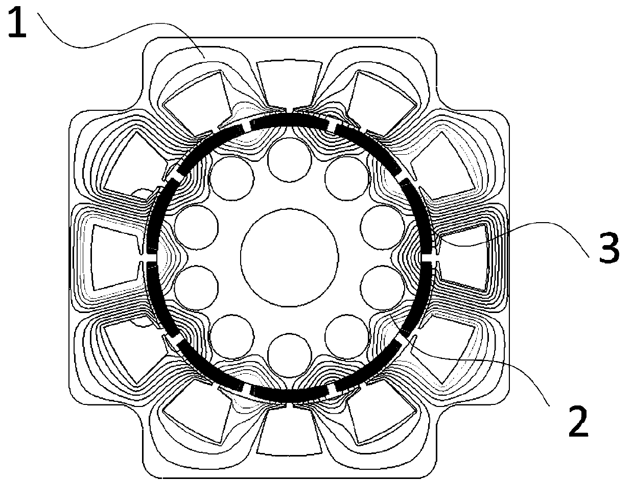
[0033] (1) Determine the rotation angle: According to the shape of the permanent magnet motor stator punching plate is square, the number of slots Q is 12, determine the rotation angle α of the stator core r is 90°;
[0034] (2) Equally divided stator core: based on the rotation angle α of the stator core r is 90°, the stator core is divided into two sections along the axial direction, and the total number of stator cores is 2;
[0035] (3) Process the stator core: stack the two stator cores separately, according to the rotation angle α r Arranged in sequence along the axial direction at 90°, laminated as a whole to complete the processing of the stator core, such as Figure 5 shown.
[0036] The stator core involved in this embodiment is ...
Embodiment 2
[0038] The specific process of the stator core manufacturing method involved in this embodiment includes three steps: determining the rotation angle, dividing the stator punching sheet equally, and processing the stator punching sheet:
[0039] (1) Determine the rotation angle: According to the shape of the permanent magnet motor stator punching plate is square, the number of slots Q is 12, determine the rotation angle α of the stator core r is 90°;
[0040] (2) Equally divided stator core: based on the rotation angle α of the stator core r is 90°, the stator core is divided into 4 sections along the axial direction, and the total number of stator cores is 4;
[0041] (3) Process the stator core: stack the 4 segments of the stator core separately, according to the rotation angle α r Arranged in sequence along the axial direction at 90°, laminated as a whole to complete the processing of the stator core, such as Figure 7 shown.
[0042] The stator iron core involved in thi...
Embodiment 3
[0044] The specific process of the stator core manufacturing method involved in this embodiment includes three steps: determining the rotation angle, dividing the stator punching sheet equally, and processing the stator punching sheet:
[0045] (1) Determine the rotation angle: According to the shape of the permanent magnet motor stator punching plate is circular, the number of slots Q is 12, determine the rotation angle α of the stator core r is 90°;
[0046] (2) Equally divided stator core: based on the rotation angle α of the stator core r is 90°, the stator core is divided into two sections along the axial direction, and the total number of stator cores is 2;
[0047] (3) Process the stator core: stack the two stator cores separately, according to the rotation angle α r Arranged in sequence along the axial direction at 90°, laminated as a whole to complete the processing of the stator core, such as Figure 9 shown.
[0048] The stator core involved in this embodiment i...
PUM
 Abstract
Description
Claims
Application Information
 - R&D
- Intellectual Property
- Life Sciences
- Materials
- Tech Scout
- Unparalleled Data Quality
- Higher Quality Content
- 60% Fewer Hallucinations
Browse by: Latest US Patents, China's latest patents, Technical Efficacy Thesaurus, Application Domain, Technology Topic, Popular Technical Reports.
© 2025 PatSnap. All rights reserved.Legal|Privacy policy|Modern Slavery Act Transparency Statement|Sitemap|About US| Contact US: help@patsnap.com