Direct-current rotary friction nano power generation device with gear meshing structure
A technology of rotating friction and nano-power generation, applied in the direction of friction generators, etc., can solve the problems of low electrostatic induction efficiency and complex structure, and achieve the effects of sufficient electrostatic induction effect, simplified device structure, and stable contact pressure
- Summary
- Abstract
- Description
- Claims
- Application Information
AI Technical Summary
Problems solved by technology
Method used
Image

Examples
Embodiment 1
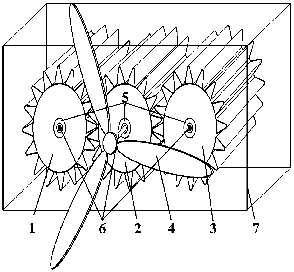
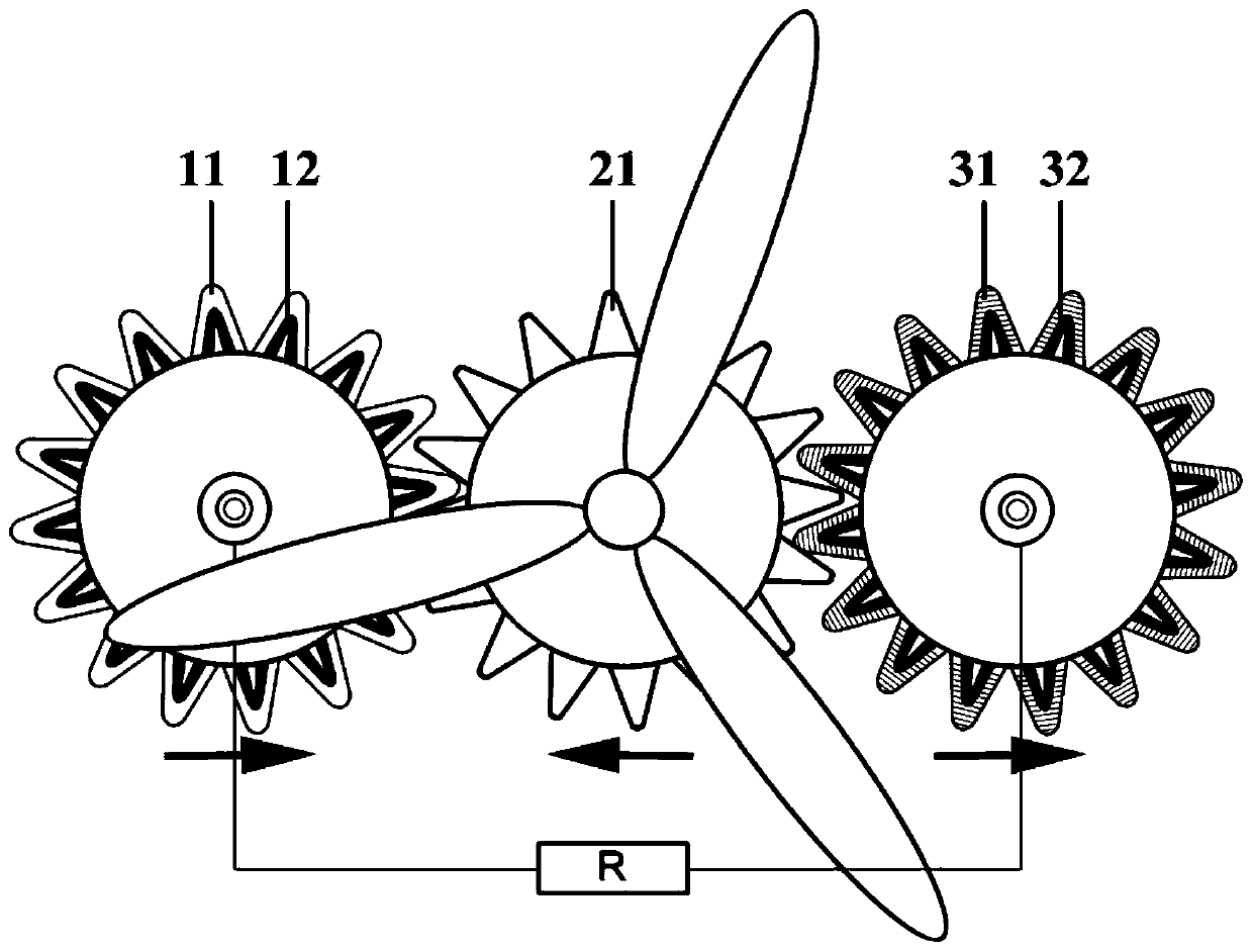
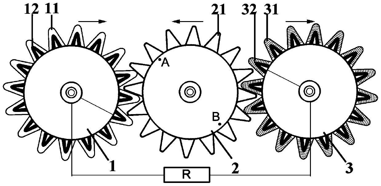
[0026] Select three customized gear assemblies made of nylon material with the same shape and size, 10 cm in diameter and 15 cm in length as the first gear assembly, the second gear assembly and the third gear assembly. For the materials of the first induction electrode and the third induction electrode, silver paste is selected and evenly coated on the surface of the teeth of the first gear assembly and the third gear assembly by brushing, and then dried with hot air. Select polytetrafluoroethylene and polyurethane solutions as the friction layer materials of the first gear assembly and the third gear assembly respectively, uniformly coat them by spraying with a spray gun, and dry them with hot air. The friction layer of the second gear assembly is the outer surface of its own nylon material. A cuboid made of plexiglass is selected as a bracket to support the entire power generation device. Choose a wind blade made of nylon to collect wind energy to provide the initial power...
Embodiment 2
[0028]Select three customized gear assemblies made of nylon material with the same shape and size, 10 cm in diameter and 15 cm in length as the first gear assembly, the second gear assembly and the third gear assembly. A cuboid made of plexiglass is selected as a bracket to support the entire power generation device. For the first induction electrode and the third induction electrode material, polythiophene conductive polymer is selected and sprayed on the teeth of the first gear assembly and the third gear assembly by atomization. Select polyvinyl chloride film and polyurethane film as friction layer materials, and use conductive adhesive to evenly adhere them to the teeth of the first gear assembly and the third gear assembly respectively. The friction layer of the second gear assembly is the outer surface of its own nylon material. Under the action of wind energy, the wind blades made of nylon rotate, and the friction surfaces of nylon, polyvinyl chloride and polyurethane ...
PUM
 Abstract
Description
Claims
Application Information