Control cabinet with good heat dissipation performance

A technology of heat dissipation performance and control cabinet, applied in the field of control cabinet, can solve the problem of easy intrusion heat dissipation performance, etc., to achieve the effect of strengthening heat dissipation effect, strengthening heat dissipation efficiency, and increasing heat dissipation speed

Pending Publication Date: 2019-11-15
刘濒遥
View PDF0 Cites 11 Cited by
  • Summary
  • Abstract
  • Description
  • Claims
  • Application Information

AI Technical Summary

Problems solved by technology

[0005] The purpose of the present invention is to provide a control cabinet with good heat dissipation performance to solve the problems of dust, rain, moisture, etc. that are easy to invade and poor heat dissipation performance in the control cabinet in the prior art.

Method used


Image

  • Control cabinet with good heat dissipation performance
  • Control cabinet with good heat dissipation performance
  • Control cabinet with good heat dissipation performance

Examples


Embodiment 1

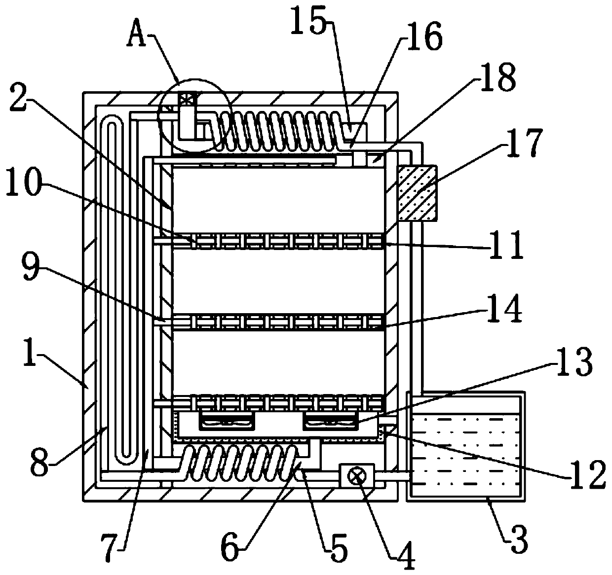
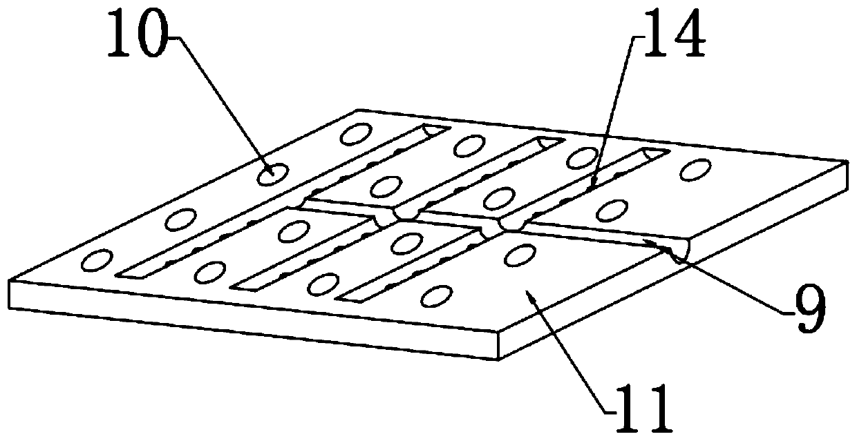
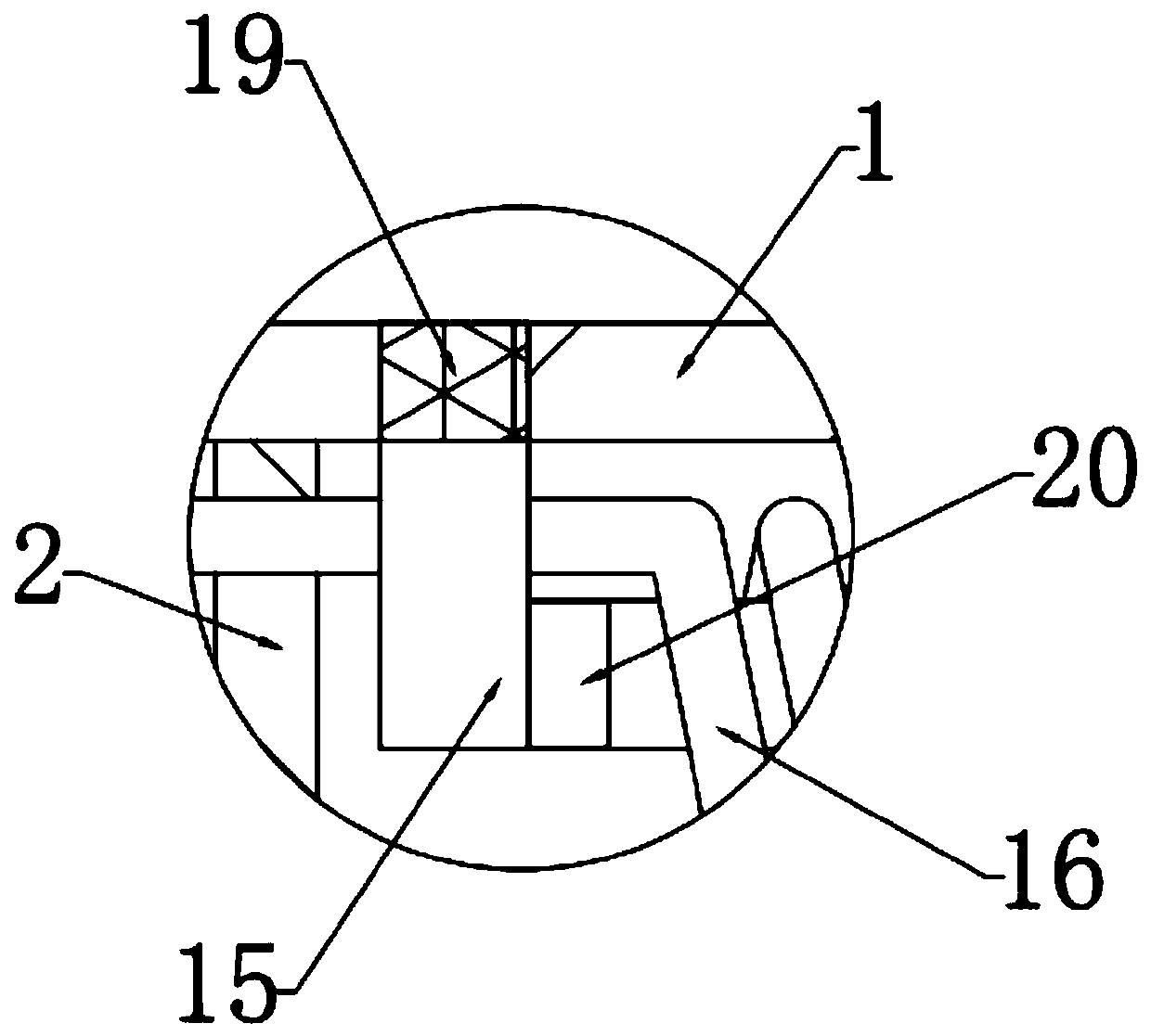
[0028] see Figure 1~3 , in an embodiment of the present invention, a control cabinet with good heat dissipation performance, including a cabinet body 1, is characterized in that a partition 2 is fixed vertically inside the cabinet body 1, and the right side of the partition board 2 is connected to the cabinet body 1, a top plate 18 is horizontally arranged, and several layers of placing plates 11 are horizontally arranged on the lower side of the top plate 18, and a cooling box 12 is fixedly connected to the lower side of the placing plate 11 on the bottom side, and the right side of the cooling box 12 is set There is a ventilation pipe passing through the cabinet body 1, a first cooling mechanism is arranged on the lower side of the heat dissipation box 12, a second cooling mechanism is arranged on the upper side of the top plate 18, and a cooling mechanism is arranged on the left side of the partition plate 2.

Embodiment 2

[0030] In this embodiment, the first cooling mechanism includes a water tank 3, an air outlet pipe 6, a first cooling pipe 5 and a fan 13, the water tank 3 is arranged on the right side of the cabinet body 1, and the air outlet pipe 6 is fixedly connected with a heat dissipation At the bottom of the tank 12, the other end of the air outlet pipe 6 passes through the partition 2 and is connected to the air delivery pipe 7. A first cooling pipe 5 is arranged on the outside of the air outlet pipe 6, and a water pump passes between the input end of the first cooling pipe 5 and the water tank 3. 4 connection, the inside top of the heat dissipation box 12 is fixedly connected with a fan 13.

[0031] In this embodiment, the second cooling mechanism includes an air inlet pipe 15 and a second cooling pipe 16, the air inlet pipe 15 is arranged on the upper side of the top plate 18, the input end of the air inlet pipe 15 is connected to the cabinet body 1, and the air inlet pipe 15 is conn...


PUM


Abstract

The invention relates to the technical field of control cabinets, in particular to a control cabinet with good heat dissipation performance. The control cabinet comprises a cabinet body in which a partition plate is arranged. A top plate is arranged between the right end of the partition plate and the cabinet body. A second cooling mechanism is arranged on the top of the top plate. A number of placement plates are arranged below the top plate. A heat dissipation box is arranged at the bottom of the bottommost placement plate. A ventilation pipe passing through the cabinet body is arranged on the right side of the heat dissipation box. A first cooling mechanism is arranged below the heat dissipation box. A cooling mechanism is arranged on the left side of the partition plate. Through the setting of the first cooling mechanism and the second cooling mechanism, the temperature of the air in the cabinet body and the air entering the cabinet body from the outside can be reduced on the basisof the original ventilation pipe, and the heat dissipation effect is greatly enhanced. Through the setting of a snakelike bend pipe, the water after heat exchange can be cooled again, and the coolingeffect of the second cooling pipe is ensured. The electrical cabinet has a good heat dissipation effect, and dust and rainwater can be prevented from entering the electrical cabinet.

Description

technical field [0001] The invention relates to the technical field of control cabinets, in particular to a control cabinet with good heat dissipation performance. Background technique [0002] The control cabinet is a common electrical equipment and an important part of the power system. The control cabinet is to assemble switchgear, measuring instruments, protective appliances and auxiliary equipment in a closed or semi-closed metal cabinet or on a screen width according to the requirements of electrical wiring. Realize power control and transmission. [0003] Various electrical modules arranged inside the electrical cabinet will generate a large amount of heat during operation, and the accumulation of a large amount of heat will cause the temperature inside the electrical cabinet to rise, thereby affecting the normal operation of the electrical cabinet. In order to dissipate the heat in time, air cooling is usually adopted, that is, the top or side panels of the electric...

Claims


Application Information

Patent Timeline
Patent Type & Authority Applications(China)
IPC IPC(8): H05K7/20
CPCH05K7/20136H05K7/20145H05K7/20181H05K7/20318H05K7/20327
Inventor 刘濒遥
Owner 刘濒遥
Why Eureka
Try Eureka