[0018] In order to make the objectives, technical solutions, and advantages of the embodiments of the present invention clearer, the technical solutions in the embodiments of the present invention will be described clearly and completely in conjunction with the accompanying drawings in the embodiments of the present invention. Obviously, the described embodiments It is a part of the embodiments of the present invention, not all the embodiments. The components of the embodiments of the present invention generally described and illustrated in the drawings herein may be arranged and designed in various different configurations. Therefore, the following detailed description of the embodiments of the present invention provided in the accompanying drawings is not intended to limit the scope of the claimed invention, but merely represents selected embodiments of the present invention. Based on the embodiments of the present invention, all other embodiments obtained by those of ordinary skill in the art without creative work shall fall within the protection scope of the present invention.
[0019] It should be noted that similar reference numerals and letters indicate similar items in the following drawings. Therefore, once an item is defined in one drawing, it does not need to be further defined and explained in the subsequent drawings.
[0020] In the description of the present invention, it should be noted that the terms "center", "upper", "lower", "left", "right", "vertical", "horizontal", "inner", "outer", etc. The indicated position or position relationship is based on the position or position relationship shown in the drawings, or the position or position relationship usually placed when the product of the invention is used. It is only for the convenience of describing the present invention and simplifying the description, rather than indicating or implying The referred device or element must have a specific orientation, be configured and operated in a specific orientation, and therefore cannot be understood as a limitation of the present invention. In addition, the terms "first", "second", "third", etc. are only used for distinguishing description, and cannot be understood as indicating or implying relative importance.
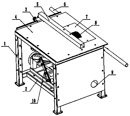
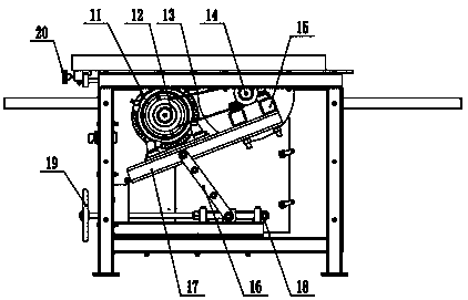
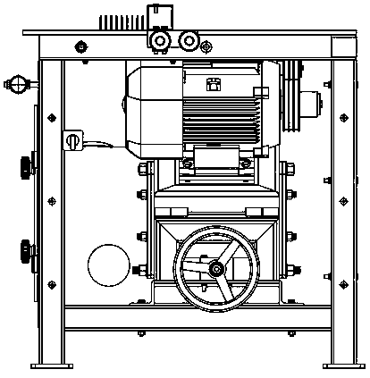
[0021] Such as figure 1 In the illustrated embodiment, the base 1 and the sawing machine body set on the base 1, the sawing machine body includes a sawing machine base 9, a saw frame 11 set on the sawing machine base 9, a main drive system 13 and a saw frame set on the saw frame 11 The hydraulic station 17 and the cooling system 18 and the electrical system 19 arranged on the side of the saw frame 11, the sawing machine base 9 is slidably connected to the base 1, and the base 1 is provided with a fixed support base 31 and a movable support base supporting the two ends of the workpiece. 3. The fixed support seat 31 and the movable support seat 3 are arranged on both sides of the sawing machine body. The height of the fixed support seat 31 and the movable support seat 3 matches the cutting height of the saw frame 11, and the sawing machine base 9 is equipped with a sawing machine that controls the rotation of the sawing machine. Rotating oil cylinder 10, movable supporting seat 3 is provided with a rotary locking device 6 supporting one end of the workpiece, fixed supporting seat 31 is provided with a fixed supporting driving device 16 supporting the other end of the workpiece; movable supporting seat 3 is provided with a supporting seat locking device at the bottom Oil cylinder 2, movable support base hydraulic station 5 is provided on the top of movable support base 3, linear guide rail 106 is provided on base 1, and movable support base 3 is provided with moving device 4 that controls the movable support base 3 to slide on linear guide rail 106; saw; The frame 11 is provided with a saw blade hydraulic tensioning device 14 for protecting the saw blade and a saw blade guide device 15 for guiding the saw blade cutting direction; between the base 1 and the sawing machine base 9 there is a longitudinal movement of the sawing machine which controls the longitudinal sliding of the sawing machine body on the base 1 Device 8, between the sawing machine base 9 and the sawing frame 11 is provided with a saw frame transverse feed device 12 that controls the saw frame 11 to move laterally on the sawing machine base 9; the base 1 is provided with an operating platform 22 which is close to the sawing machine body. A feed receiving device 21 is provided on the base 9 of the sawing machine, and a chip removal device 20 is provided under the feed receiving device 21.
[0022] The sawing machine rotary cylinder 10 includes a rotary base 101 and a locking cylinder 104 mounted on the sawing machine base 9. The rotary base 101 is provided with a rotary shaft 102, a rotary cylinder 105 and a rotary encoder 103. The rotary shaft 102 is connected to the sawing machine base 9 to drive The saw frame 11 rotates.
[0023] The rotary locking device 6 includes a left-end housing 65, a left-end spindle 61 arranged in the left-end housing 65, a left-end center 63 and a left-end three-jaw chuck 62 arranged on the right end of the left-end spindle 61 to cooperate with each other, and a left-end spindle 61 arranged on the left end of the left-end spindle 61 Rotary locking disc 64; fixed support driving device 16 includes a right end housing, a right end spindle arranged in the right end housing, a right end center and a right three-jaw chuck arranged on the left end of the right spindle to cooperate with each other, and arranged on the right end of the right spindle to cooperate with each other Rotating motors and rotating gears and encoders.
[0024] When the present invention is used, the electrical system, the hydraulic station of the movable support base and the hydraulic station of the saw frame are started, one end of the workpiece is hoisted into the fixed support driving device, the support base is released to lock the oil cylinder, and the moving device drives the movable support base to move forward to move the workpiece The other end is installed in the rotary locking device and the driving device of the movable support seat to manually clamp the workpiece; the rotary cylinder of the sawing machine is loosened and rotated to the direction of 90° with the axis of the workpiece, the rotary cylinder of the sawing machine is locked, and then the saw frame is on the saw frame Driven by the transverse feed device, feed motion on the base of the sawing machine to perform sawing perpendicular to the axis of the workpiece at 90°, sawing to the specified size, the saw frame retracts to the original position, the sawing machine rotating cylinder is loosened and rotated to the specified After the angle is stopped, the sawing machine's rotating cylinder is locked, and then the sawing machine's longitudinal moving device drives the saw frame to move to a specified distance from the first knife; the saw frame is driven by the saw frame transverse feed device to feed on the sawing machine base. Sawing at the specified angle direction, sawing to the specified size, and the saw frame retracted to the original position; one side saw is completed; the fixed support driving device and the rotary locking device are released, and the workpiece is rotated by the fixed support driving device for 90 °, the next position and the workpiece axis and the specified angle of the sawing, and so on, until the last bevel sawing is completed.
[0025] The sawing machine for wood cutting boards of the present invention has a reasonable design and does not require manpower to deliver the wood to the worktable. It only needs to place the wood in the feeding arc to realize easy feeding. After feeding, the first telescopic cylinder Lowering, the middle pole is clamped to the wood to realize the centering. The large amount of wood chips generated when the band saw is sawing is greatly absorbed and collected by the wood chip suction collection device, which optimizes the production environment and improves the staff Production safety, reduce the probability of safety accidents, indirectly improve the work efficiency of the staff, reduce the cleaning cost, and the centering effect is obvious, the sawing accuracy of the sawing machine is improved, the installation is convenient, the operation is also very simple, and it has a structure It is compact, easy to carry and transport, and it can adjust the height of the saw blade exposed to the work surface conveniently and quickly to achieve the characteristics of more types of wood wire processing work efficiently.
[0026] The above specific embodiments are only specific cases of the present invention. The scope of patent protection of the present invention includes but is not limited to the product form and style of the above specific embodiments, any sawing machine for wood cutting boards that meets the claims of the present invention and any Appropriate changes or modifications made by those of ordinary skill in the technical field shall fall within the scope of patent protection of the present invention.