A turning mechanism and turning method suitable for an assembled underpass tunnel

A flipping mechanism and prefabricated technology, applied in tunnels, tunnel linings, shaft equipment, etc., can solve the problems of low flipping efficiency, easy damage to prefabricated components, and great construction hazards, so as to reduce prefabrication costs, facilitate assembly and construction, and ensure structural integrity. quality effect

Active Publication Date: 2020-06-30
成都城投城建科技有限公司
View PDF9 Cites 0 Cited by
  • Summary
  • Abstract
  • Description
  • Claims
  • Application Information

AI Technical Summary

Problems solved by technology

[0006] The object of the present invention is to provide a method that is suitable for turning over tunnel components and can improve Overturning efficiency, and reduce the risk of construction overturning device

Method used


Image

  • A turning mechanism and turning method suitable for an assembled underpass tunnel
  • A turning mechanism and turning method suitable for an assembled underpass tunnel
  • A turning mechanism and turning method suitable for an assembled underpass tunnel

Examples


Embodiment 1

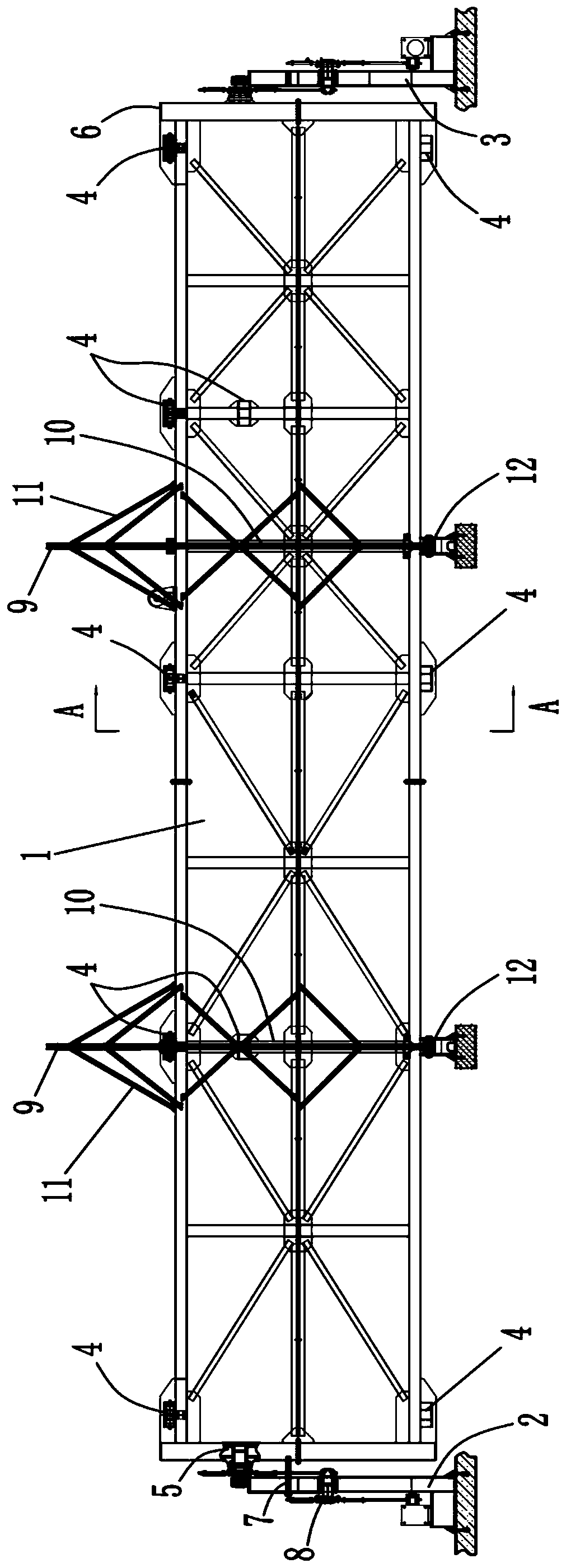
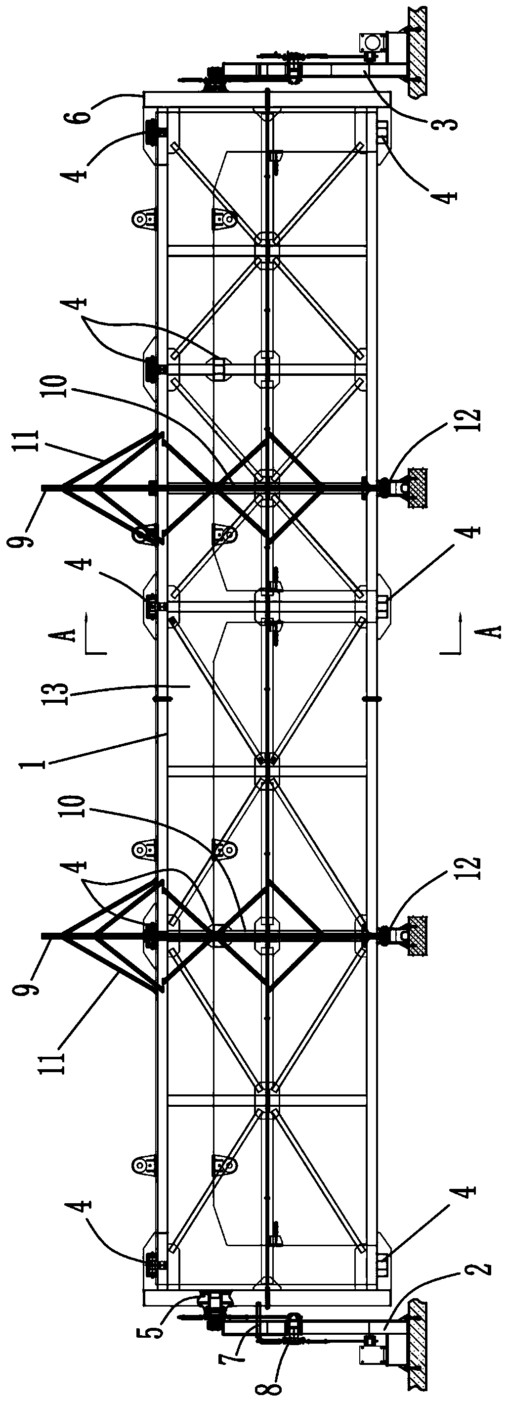
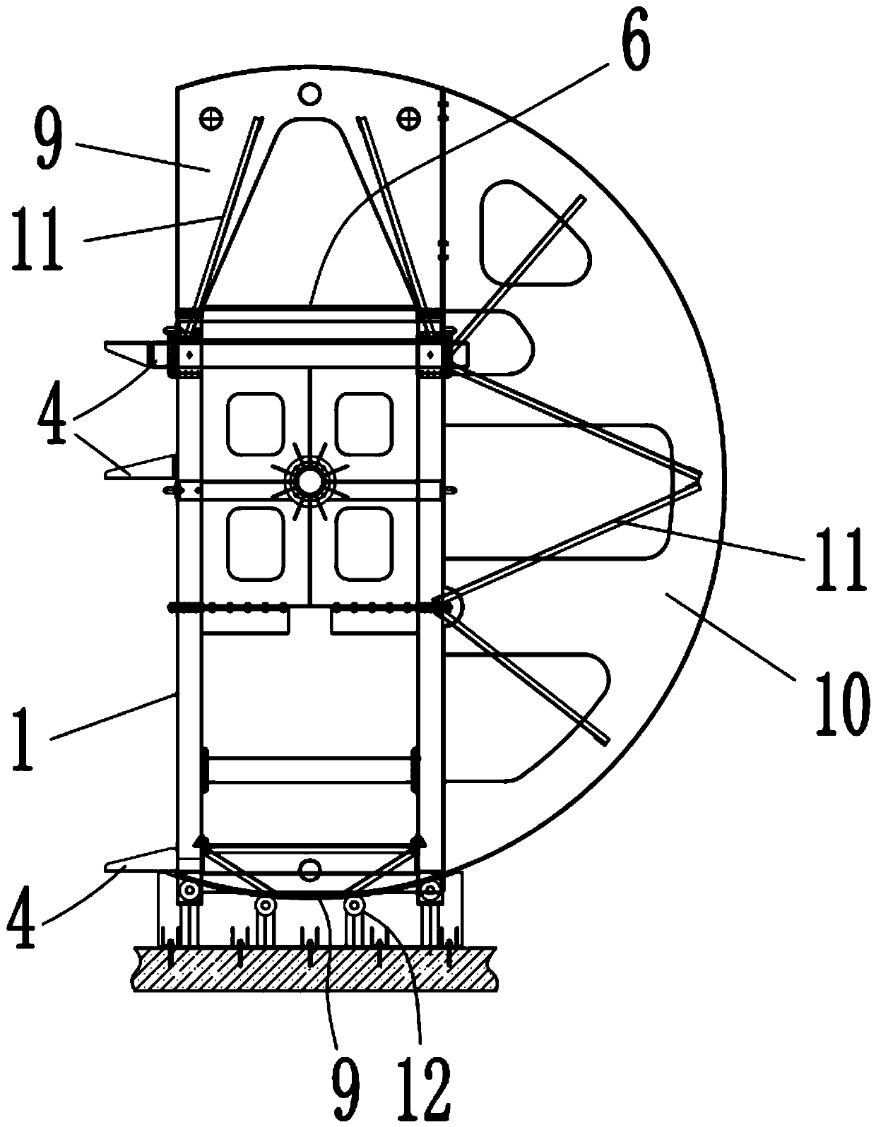
[0036] Example 1, such as Figure 1-3 Shown:

[0037] A turning mechanism suitable for a fabricated underpass tunnel, comprising a clamping part 1 for clamping the prefabricated member 13 and a first supporting seat 2 and a second supporting seat 3 for supporting the clamping part 1, so The clamping member has a clamping space through which the prefabricated member 13 can penetrate vertically. The first support base 2 and the second support base 3 are arranged opposite to each other and rotate and cooperate with the support member. A supporting base 2 and / or a second supporting base 3 is also provided with a driving member for driving the clamping member 1 to rotate, and a plurality of supporting rods passing through the clamping space are also provided on the clamping member 1 4. The support rod 4 is used to support the prefabricated member 13 in the vertical direction, and the support rod 4 is detachably connected to the clamping component 1.

[0038] In the turning mechanism o...

Embodiment 2

[0048] Example 2, such as Figure 1-3 Shown,

[0049] A method for prefabricating tunnel frame members using the above-mentioned turning mechanism,

[0050] Step 1. Design steps: In the design stage, divide the frame members of the tunnel to be constructed into W-frame and M-frame in the horizontal direction;

[0051] Step 2: Making the pouring mold: make W-frame pouring mold or M-frame pouring mold;

[0052] Step three, pouring: pouring the W-frame and M-frame in the W-frame pouring mold or M-frame pouring mold in step two;

[0053] Step four, component flip:

[0054] When the pouring mold is a W-frame pouring mold, hoist the poured M-frame into the clamping space of the turning mechanism, and then start the driving device of the turning mechanism to turn the clamping part 1 through 180°, so that the M-frame is installed form;

[0055] When the pouring mold is an M-frame pouring mold, hoist the poured W-shaped frame into the holding space of the turning mechanism, and then start the dr...


PUM


Abstract

The invention relates to the technical field of construction engineering, specifically relates to a turnover mechanism suitable for an assembly type under-crossing tunnel and a turnover method. The turnover mechanism comprises a clamping part, a first supporting base and a second supporting base, wherein a clamping component is provided with a clamping space which a prefabricated component can penetrate in the vertical direction, the first supporting base and the second supporting base are oppositely arranged and are rotationally matched with a supporting part, the first supporting base and / orthe second supporting base is further provided with a driving part for driving the clamping part to rotate, a plurality of supporting rods penetrating through the clamping space are further arrangedon the clamping part, the supporting rods are used for supporting the prefabricated component in the vertical direction, and the supporting rods and the clamping part are detachably connected. According to the turnover mechanism, the turnover efficiency is greatly improved, the labor intensity of workers in the turnover process is also reduced, the damage risk of the prefabricated component is reduced, and the construction risk of workers is reduced as well.

Description

Technical field [0001] The invention relates to the technical field of construction engineering, in particular to an overturning mechanism and an overturning method suitable for an assembled underpass tunnel. Background technique [0002] In the field of construction engineering technology, in the construction of urban underpass tunnels, tunnel components are usually cast in situ and prefabricated. For cast-in-situ methods, due to the need for a longer maintenance period, it is not conducive to shortening the construction period. For tunnels under tunnels, prefabricated construction methods are usually adopted. [0003] For the prefabrication of tunnel components by prefabrication, although the construction period can be greatly shortened, in the further construction design, the inventor found that the current tunnel component prefabrication construction still has shortcomings, specifically: [0004] As the tunnel components are usually large in volume and weight, the turning proces...

Claims


Application Information

Patent Timeline
Patent Type & Authority Patents(China)
IPC IPC(8): B66C13/08E21D11/08
CPCB66C13/08E21D11/08
Inventor 杨程陈禹唐伟于淼韩尚游许光文税流洲
Owner 成都城投城建科技有限公司
Why Eureka
Try Eureka