
Main return air duct reconstruction method suitable for concentrated return air in downhole

A return air duct and centralized technology, applied in separation methods, chemical instruments and methods, ventilation of mines/tunnels, etc., can solve problems such as no total air return duct, achieve short renovation period, save engineering and equipment investment, and be convenient The effect of ventilation management

Active Publication Date: 2019-11-19
CINF ENG CO LTD
View PDF11 Cites 2 Cited by
  • Summary
  • Abstract
  • Description
  • Claims
  • Application Information

AI Technical Summary

Problems solved by technology

However, this structure has no main air return channel for centralized return air in the mine, so the main fan can only be installed at the wellhead of the return air shaft or fans can be installed in the middle section of each return air underground, which is not suitable for the wellhead of the return air shaft or the Shimen fan for the return air in the middle section of the underground mine. Mutual interference, and mine ventilation system reconstruction of the total return air duct without centralized return air underground

Method used


Image

  • Main return air duct reconstruction method suitable for concentrated return air in downhole
  • Main return air duct reconstruction method suitable for concentrated return air in downhole
  • Main return air duct reconstruction method suitable for concentrated return air in downhole

Examples


Embodiment 1

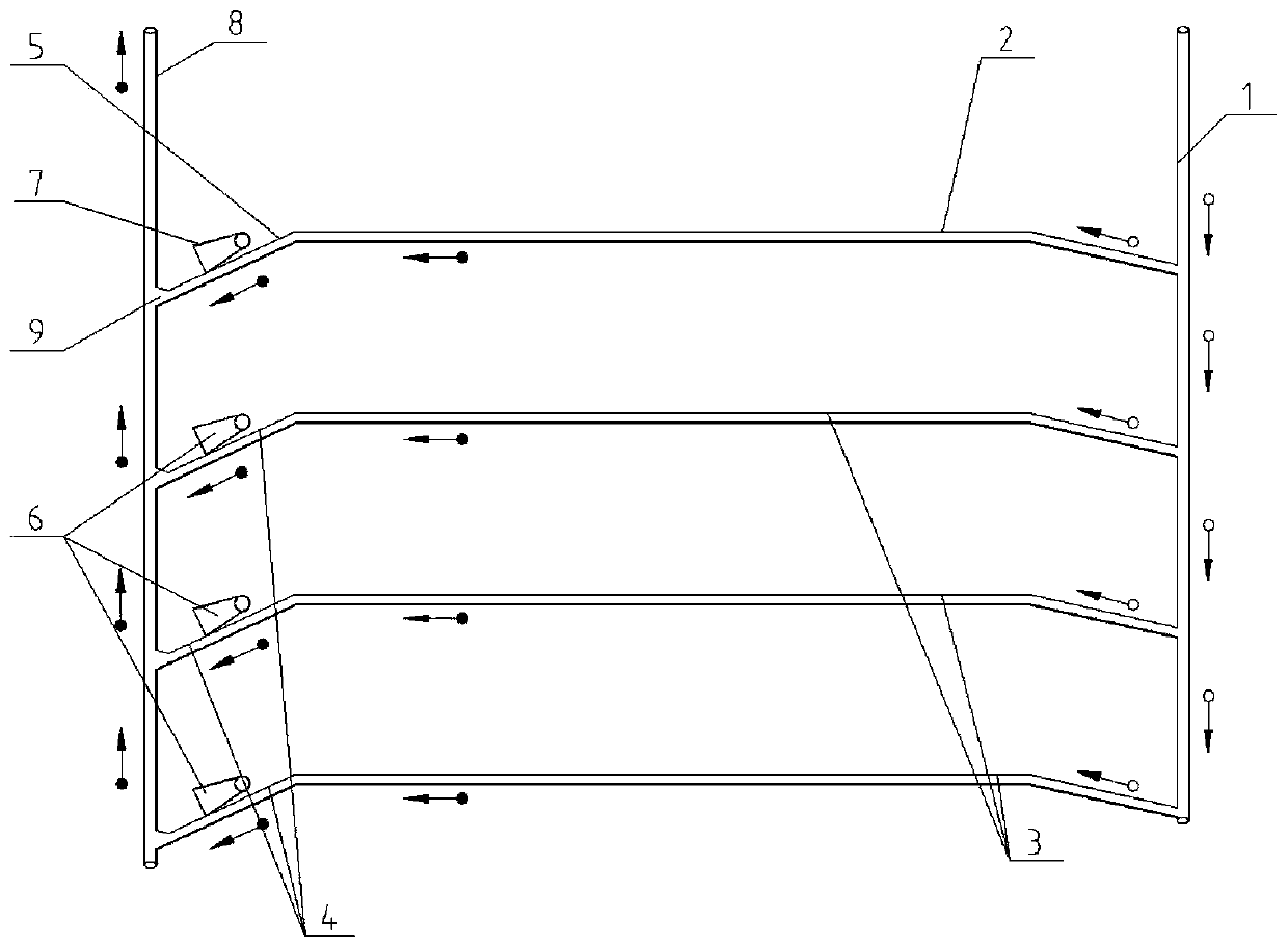
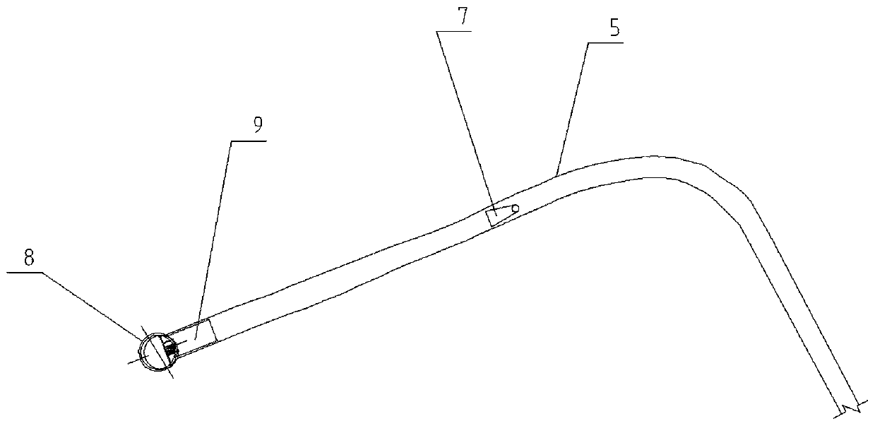
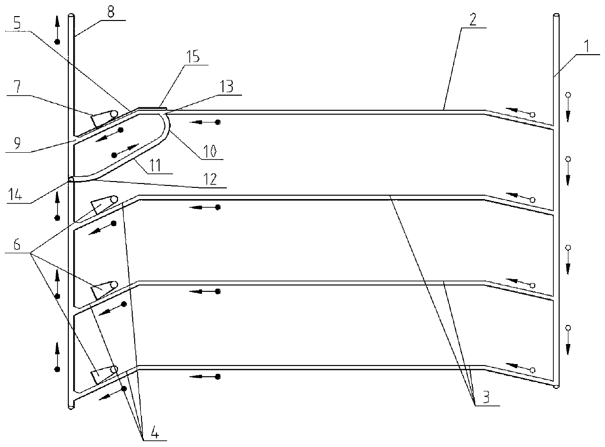
[0055] From figure 1 and figure 2 It can be seen that the original ventilation system applicable to the underground concentrated air return of the present invention includes an air inlet shaft 1, the shallowest middle section air inlet lane 2, the deep middle section air inlet lane 3, the deep middle section return air stone gate 4, the shallowest middle section air inlet lane Wind stone door 5, deep return air Shimen machine station fan 6, the shallowest middle section return air Shimen machine station fan 7 and return air shaft 8, the shallowest middle section air inlet lane 2 is located in the shallowest part of the mine, and the deepest middle section air inlet lane 3 Located below the shallowest middle air inlet lane 2, the air inlet ends of the shallowest middle air inlet lane 2 and the deep middle air inlet lane 3 are connected to the air inlet shaft 1, and the return air end of the shallowest middle air inlet lane 2 The return air shaft 8 is communicated with the ret...

Embodiment 2

[0086] From Figure 10 to Figure 12 It can be seen that the difference between this embodiment and Embodiment 1 is that the platform of this embodiment adopts a reinforced concrete beam-slab structure, the concrete strength grade is not less than C30, the platform 19 includes a main beam 20 and a secondary beam 21, and the main beam 20 Excavate the existing well wall 22 of the air return shaft to form a beam nest 29, and the size of the beam nest 29 is determined on site according to the specifications of the main beam 20;

[0087] The main beam 20 and the secondary beam 21 adopt a well-shaped arrangement, the main beam 20 is arranged horizontally, and the secondary beam 21 is arranged vertically, or the main beam 20 is arranged longitudinally, and the secondary beam 21 is arranged horizontally. The distance between the main beam 20 and the secondary beam 21 is the same, and the distance range 0.8-1.5m; concrete is poured around the main beam 20 and the secondary beam 21 to fo...


PUM

PropertyMeasurementUnit
Lengthaaaaaaaaaa
Thicknessaaaaaaaaaa

Abstract

The invention discloses a main return air duct reconstruction method suitable for concentrated return air in a downhole. The reconstruction method comprises the steps of S1, designing the reconstruction scheme of a main return duct; S2, driving a return air ramp in communication with a shallowest part middle stage return air stone door; S3, driving a new return air horse head door to communicate with a lower arc section and a return air well; S4, expanding the brush on a return air stone door between the upper opening of the return air ramp and a shallowest part middle stage return air horse head door; S5, arranging a platform used for sealing a rockshaft of the return air well; S6, driving a main fun chamber; S7, arranging a main fun in the main fun chamber; and S8, arranging a spraying device in a total return air duct at the exit of the main fan in the downhole to wash and purify polluted air. According to the reconstruction method, the problem of mutual interference caused by the parallel connection of a multi-middle stage return air stone door blower in the downhole under the condition of the absence of a centralized return blower station is solved effectively, the difficult problem that the main fan cannot be installed in the wellhead of the return air well due to land expropriation, environmental protection or geographical reasons can be solved, the reconstruction methodhas the little influence on an existing ventilation system, and environmental protection is achieved.

Description

technical field [0001] The invention belongs to the technical field of ventilation in underground metal mines and non-metallic mines, and in particular relates to a method for transforming a main return air passage suitable for underground concentrated return air. Background technique [0002] As metal and non-metallic mines are gradually shifted from shallow to deep mining, some old mines failed to install main fans at the head of the return air shaft due to land acquisition, environmental protection or geographical reasons. The main return air stone gate is not set, and the air return side of the system only installs fans at the return air stone gates in the middle sections of the underground to discharge the dirty air to the return air shaft and return to the surface. However, as several new mid-sections in the deep part of the mine were gradually put into production, and at the same time, the closure of the original old mid-sections in the shallow part was delayed, resul...

Claims


Application Information

Patent Timeline
IPC IPC(8): E21F1/00E21F1/10B01D47/06B01D53/00
CPCB01D47/06B01D53/00B01D2257/302B01D2257/304B01D2257/40E21F1/00E21F1/006E21F1/10
Inventor 尤祎陈建双刘杰
Owner CINF ENG CO LTD
Learn More