kW-grade supercritical carbon dioxide radial flow type turbine structure with flow dividing blades

A technology of splitting blades and carbon dioxide, which is applied in the direction of steam engine devices, stators, engine components, etc., can solve the problems that the blades are susceptible to large aerodynamic loads, the aerodynamic performance of the turbine is affected, and the safe operation of the turbine is unfavorable, so as to achieve a wide range of engineering application prospects , Improving the equal entropy efficiency of the turbine, and the effect of compact structure

Pending Publication Date: 2019-11-19
NO 719 RES INST CHINA SHIPBUILDING IND +1
View PDF6 Cites 0 Cited by
  • Summary
  • Abstract
  • Description
  • Claims
  • Application Information

AI Technical Summary

Problems solved by technology

At present, the research on radial flow turbines using supercritical carbon dioxide as the working fluid is increasing year by year. However, due to the high density of the working fluid, the size of the supercritical carbon dioxide turbine is small, and it is easy to form a Large secondary flow loss, which in turn affects the aerodynamic performance of the turbine
At the same time, the blades are easily subjected to a large aerodynamic load, which in turn produces a large equivalent stress, which is not conducive to the safe operation of the turbine.

Method used


Image

  • kW-grade supercritical carbon dioxide radial flow type turbine structure with flow dividing blades
  • kW-grade supercritical carbon dioxide radial flow type turbine structure with flow dividing blades
  • kW-grade supercritical carbon dioxide radial flow type turbine structure with flow dividing blades

Examples


Embodiment Construction

[0023] The present invention is described in more detail below in conjunction with accompanying drawing:

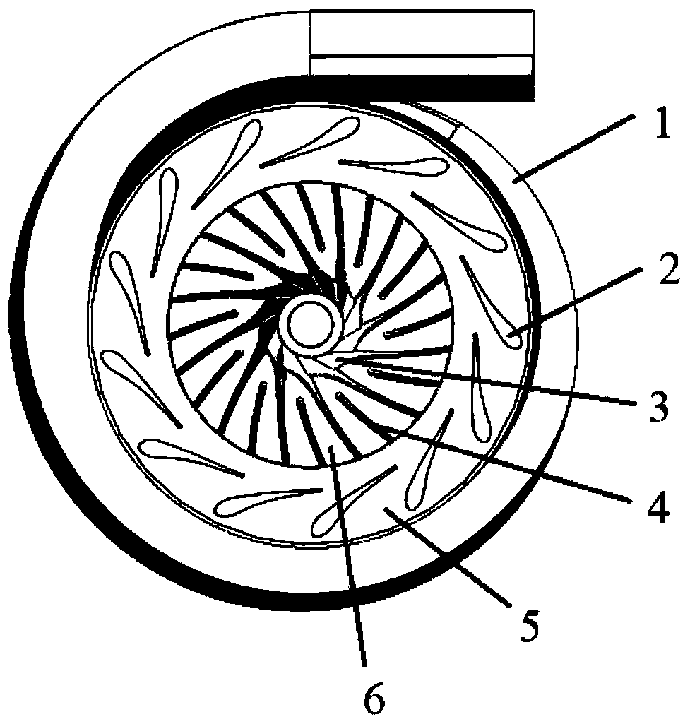
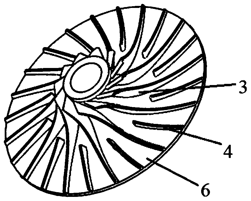
[0024] combine figure 1 and figure 2 , a kW-class supercritical carbon dioxide radial turbine structure with splitter blades provided by the present invention includes a volute 1, a stationary blade cascade 2, a movable blade cascade 3 and a splitter blade 4, wherein the splitter blade 4 is installed on the corresponding Between two adjacent movable blade cascades 3 , two adjacent stationary blade cascades 2 form a stationary blade cascade flow channel 5 , and a movable blade cascade flow channel 6 is formed between the movable blade cascade 3 and the splitter blade 4 . When working, the supercritical carbon dioxide working medium enters from the volute 1, and the gas is evenly distributed from the volute 1 to the flow channel 5 of the stator cascade. The pressure of the working medium gradually decreases in the flow channel 5 of the stationary blade cascade, and the f...


PUM


Abstract

The invention discloses a kW-grade supercritical carbon dioxide radial flow type turbine structure with the flow dividing blades. A volute, fixed blade grids, movable blade grids and the flow dividingblades are included, wherein the fixed blade grids, the movable blade grids and the flow dividing blades are arranged in the volute; each flow dividing blade is arranged between every two adjacent movable blade grids; each fixed blade grid flow channel is formed between every two adjacent fixed blade grids, and movable blade grid flow channels are formed between the movable blade grids and the flow dividing blades; in work, supercritical carbon dioxide work media enter the structure from the volute, the gas is uniformly allocated into the fixed blade grid flow channels by the volute, the pressure of the work media in the fixed blade grid flow channels is gradually lowered, and the flow speed is gradually increased; and then the supercritical carbon dioxide work media enter the movable blade grid flow channels, in the movable blade grid flow channels, the supercritical carbon dioxide work media push an impeller to rotate and output work, and finally discharging in the axial direction is achieved. In the kW-grade supercritical carbon dioxide radial flow type turbine structure with the flow dividing blades, due to the scheme of adding of the flow dividing blades and improvement of ageometrical angle of an impeller inlet, the pneumatic efficiency of the radial flow type turbine structure is substantially improved while the running safety is guaranteed, and important engineering significance and broad application prospects are achieved.

Description

technical field [0001] The invention belongs to the technical field of supercritical carbon dioxide radial flow turbines, and in particular relates to a kW-level supercritical carbon dioxide radial flow turbine structure with splitter blades. Background technique [0002] As the world's energy reserves continue to decrease and environmental pollution is becoming more and more serious, energy conservation and emission reduction has become an important direction of development. As a common substance in the atmosphere, carbon dioxide is very easy to obtain. At the same time, compared with the traditional working medium water vapor, the critical point pressure and temperature of carbon dioxide are lower and easier to reach. In the supercritical state, carbon dioxide has the characteristics of high density, low viscosity, strong fluidity, strong working ability, and low system loss. In addition, the cycle using supercritical carbon dioxide as the working medium has the advantag...

Claims


Application Information

Patent Timeline
Patent Type & Authority Applications(China)
IPC IPC(8): F01D9/04F01D15/10F01K7/32F01K25/10
CPCF01D9/041F01D15/10F01K7/32F01K25/103
Inventor 谢永慧林原胜施东波赵振兴王雨琦马灿戴春辉吴君
Owner NO 719 RES INST CHINA SHIPBUILDING IND
Why Eureka
Try Eureka