Synchronous clutch

A clutch and actuator technology, applied in clutches, mechanical drive clutches, mechanical equipment, etc., can solve problems such as high dynamic load, uneven rotation, and unexpected vehicles

Pending Publication Date: 2019-11-19
HOERBIGER ANTRIEBSTECHN HLDG
View PDF1 Cites 0 Cited by
  • Summary
  • Abstract
  • Description
  • Claims
  • Application Information

AI Technical Summary

Problems solved by technology

However, these auxiliary units usually have high rotational non-uniformity or variable loads, which can lead to excessively high dynamic loads They can in turn cause the friction clutch to slip (durchruschen) and thus can lead to an unintended and therefore unstable operating state of the vehicle

Method used


Image

  • Synchronous clutch
  • Synchronous clutch
  • Synchronous clutch

Examples


Embodiment Construction

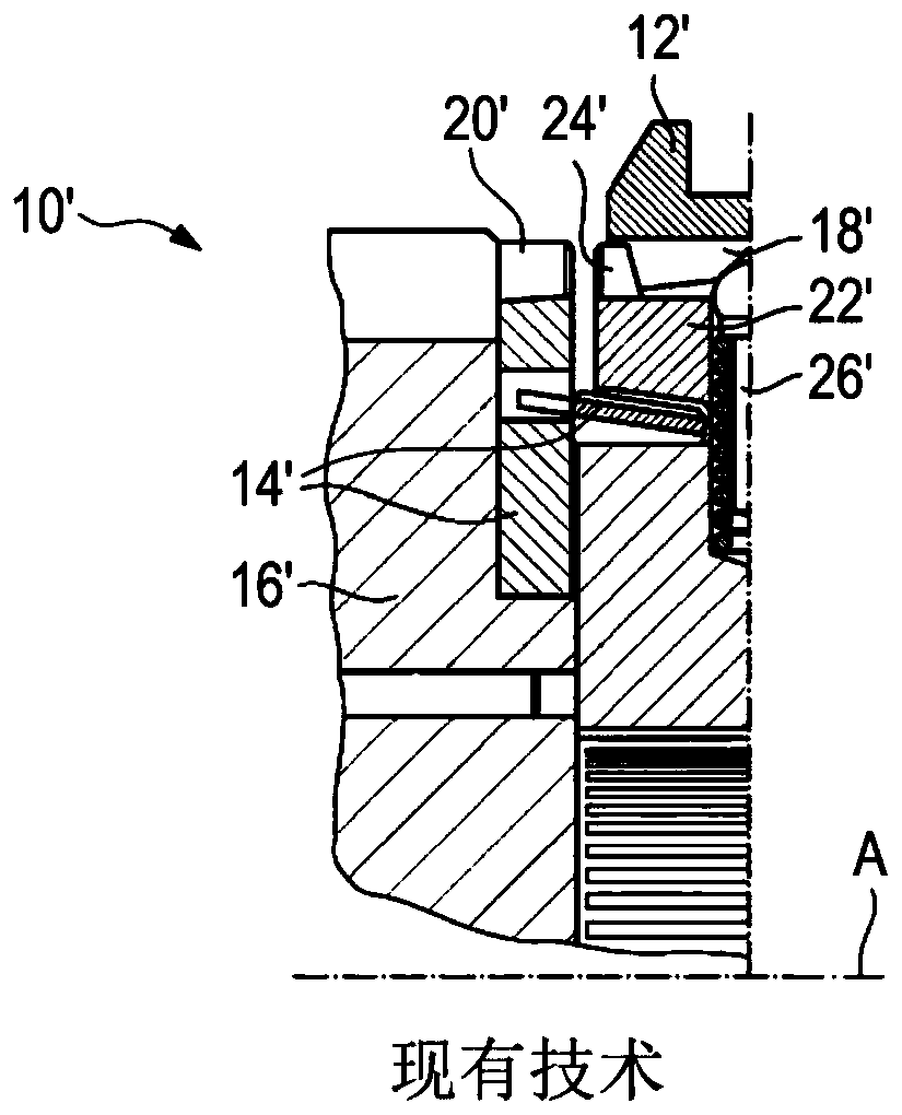
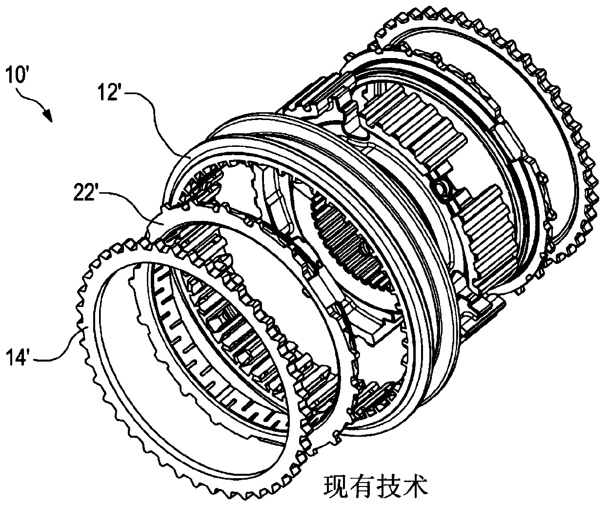
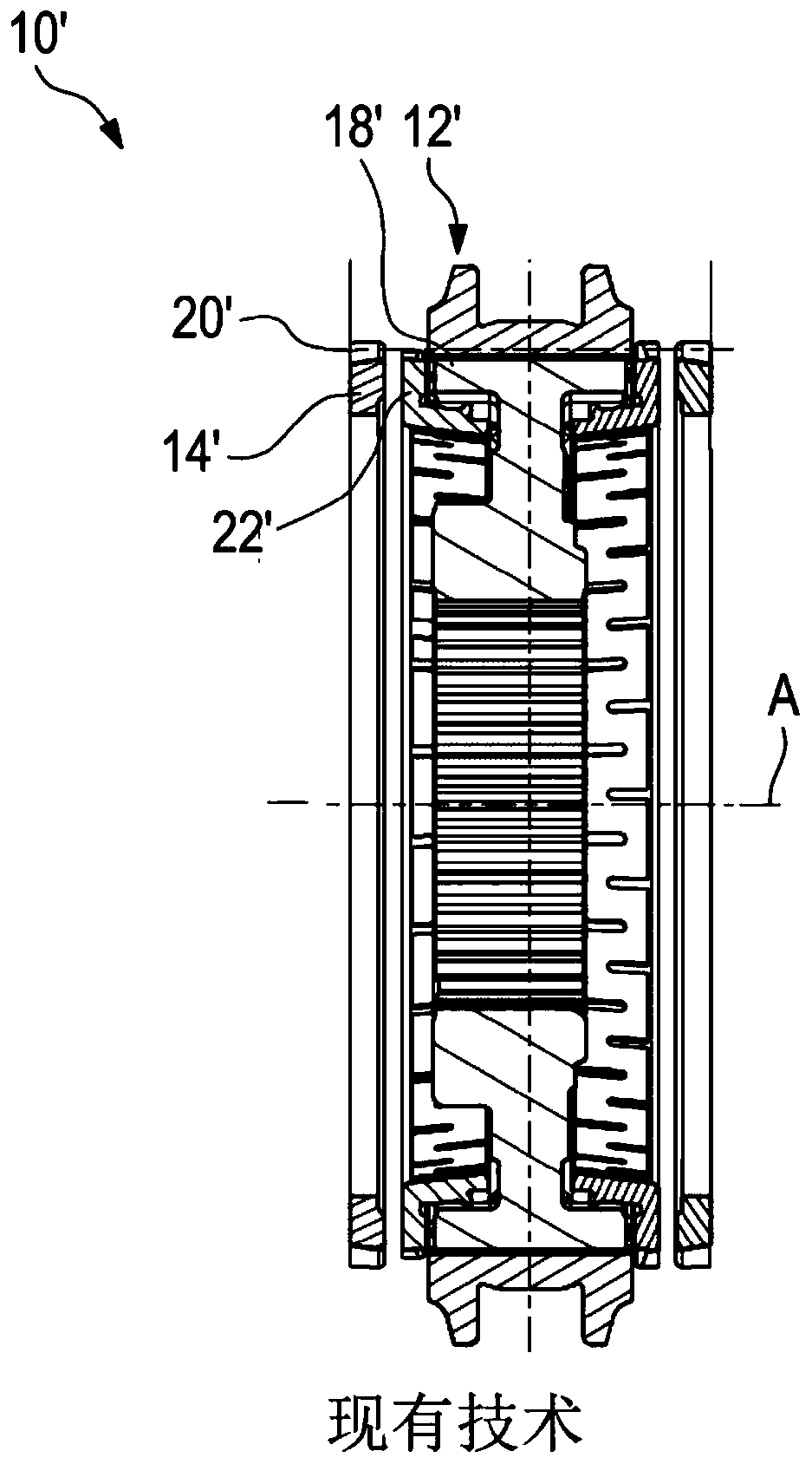
[0061] Figures 1 to 3 Shown is a well-known synchronous clutch 10' for controlling transmissions, which has a sliding sleeve 12' movable along axis A, which rotates non-rotatably with a shaft not shown in detail. Furthermore, the synchronous clutch 10' comprises a clutch body 14' configured as a clutch plate, which is firmly connected to a driven wheel 16' of the control transmission. The driven wheel 16' is rotatably fitted on the shaft as a loose wheel and can be connected to this shaft in a rotationally fixed manner via a sliding sleeve 12'.

[0062] The sliding sleeve 12' has an internal toothing with sliding sleeve teeth 18', while the clutch body 14' has an external toothing with clutch body teeth 20'.

[0063] In order to carry out the rotational speed synchronization and the subsequent engagement process in which the sliding sleeve teeth 18 ′ engage in the interspaces of the clutch body teeth 20 ′, a synchronization unit is provided which comprises a synchronization ...


PUM


Abstract

The invention relates to a synchronous clutch (10) for switchably coupling an auxiliary unit to an engine, in particular an internal combustion engine. The invention relates to a clutch comprising a sliding sleeve (12), an output-side clutch body (14) having clutch body teeth which can be engaged with internal teeth of the sliding sleeve (12), and a synchronization unit. A pre-tensioning device (128) presses the clutch into the closed position in a normal state. An actuator may disconnect the clutch. The sliding sleeve teeth and/or the clutch body teeth are wedge-shaped.

Description

technical field [0001] The invention relates to a synchronizer clutch, in particular for switchably coupling an auxiliary unit with an internal combustion engine, in particular a compressor with the internal combustion engine. Background technique [0002] For reasons of efficiency, air compressors for supplying compressed air to, for example, brake systems in trucks are usually designed in such a way that they can be decoupled from the internal combustion engine by means of a clutch unit. For safety reasons it is important that the clutch unit is closed (normally closed, English: “normally closed”) in the normal state in order to ensure a compressed air supply to the brake system in the event of a fault. [0003] Conventional solutions for decoupling such an air compressor are typically by means of conventional friction clutches preloaded with multiple spring sets, since thus the Synchronization of the rotational speeds can be achieved in a frictional manner. However, the...

Claims


Application Information

Patent Timeline
Patent Type & Authority Applications(China)
IPC IPC(8): F16D23/04
CPCF16D23/04F16D2023/0656F16D2023/0631F16D2023/0625F16D23/06F16D2023/0693
Inventor 帕特里克·费舍尔彼得·K·埃克特勒克里斯多夫·特劳特王立舒罗伯特·吕克英格尔尤尔根·沃尔夫迈克尔·赫希特尔久罗·卡拉巴
Owner HOERBIGER ANTRIEBSTECHN HLDG
Why Eureka
Try Eureka