
Normal-pressure spraying test table

A spray test, atmospheric pressure technology, applied in the testing of mechanical parts, the testing of machine/structural parts, measuring devices, etc., can solve the problems of measurement deviation, effective processing, measurement error, etc., to optimize the bench structure, prevent liquid The effect of drop bounce and improving experimental efficiency

Inactive Publication Date: 2019-11-19
JIANGSU UNIV OF SCI & TECH
View PDF7 Cites 2 Cited by
  • Summary
  • Abstract
  • Description
  • Claims
  • Application Information

AI Technical Summary

Problems solved by technology

At present, the problems existing in the test bench are mainly concentrated in two aspects: (1) the nozzle mechanism of the test bench does not have three-dimensional movement capability, and cannot be applied to the measurement of multiple measurement planes and nozzles with different configurations; (2) the droplet in the test bench is not considered Scattering phenomenon, there is no effective treatment of the droplets downstream of the nozzle, that is, the droplets at the collection platform. On the one hand, some droplets enter the measurement area for the second time, and on the other hand, the dispersion phenomenon occurs in the measurement area, especially in the measurement of large flow nozzles. Affect the accuracy of optical measurement, which will bring deviations to the measurement. For example, the spray test bench developed by Dr. Liu Juan of the National Did not take into account the droplet splashing and rebounding during the measurement, which will inevitably bring errors to the measurement (Liu Juan. Experimental and simulation research on the process of rotating cone liquid film breakup [D]. Changsha: National University of Defense Technology, 2012.)

Method used


Image

  • Normal-pressure spraying test table
  • Normal-pressure spraying test table
  • Normal-pressure spraying test table

Examples


Embodiment Construction

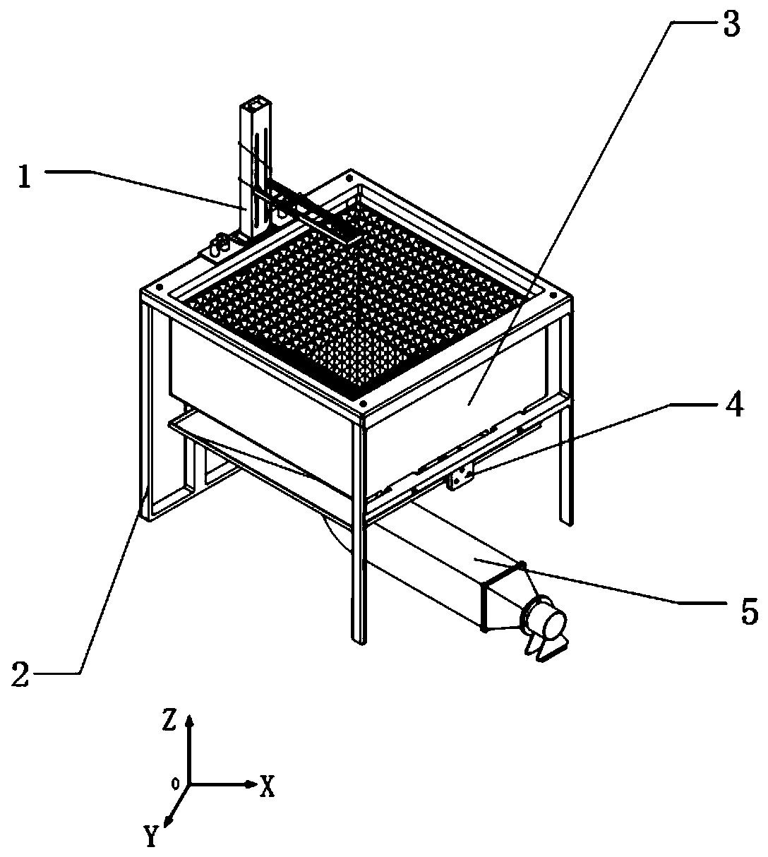
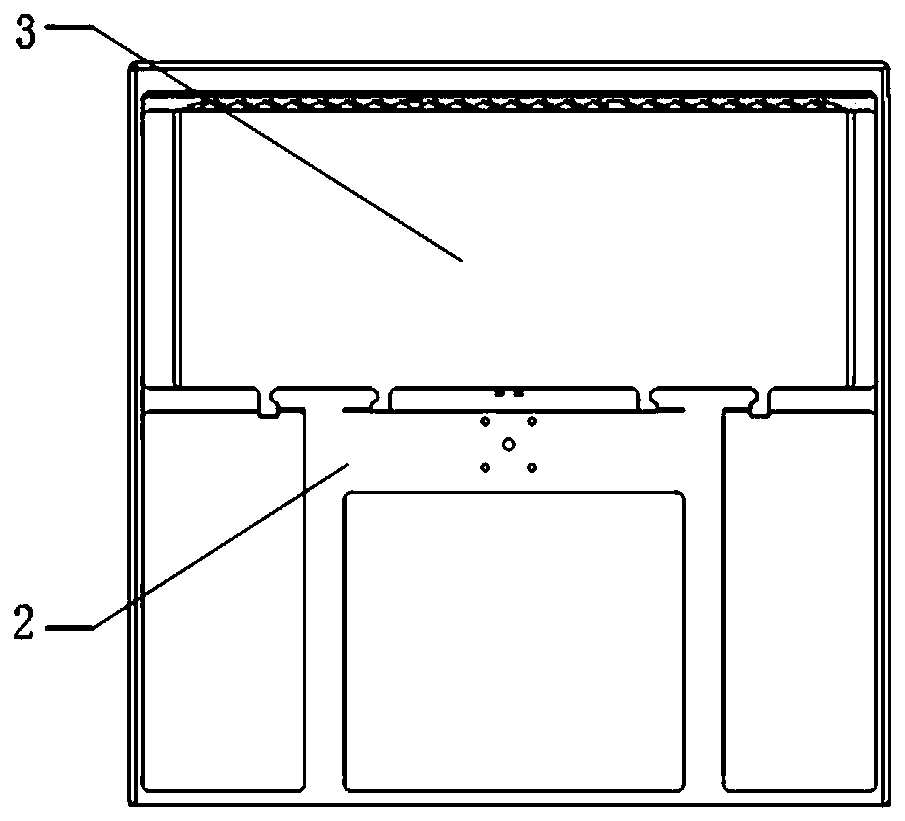
[0016] Such as figure 1 As shown, the present invention is made of stainless steel plate, the size is 1100mm in length, 1100mm in width, and 1000mm in height. From top to bottom, it consists of nozzle adjustment table 1, test bench frame 2, collection table 3, ball screw slide table 4, and ventilation The device 5 is composed of; the nozzle adjustment table 1 is arranged on one side of the test bench frame 2, the collection table 3 is embedded in the frame of the test bench frame 2, and the ball screw slide table 4 is connected to the bracket 11 and the collection table through a slider 3 are connected, and the air exhaust device 5 is located below the collection table 3.

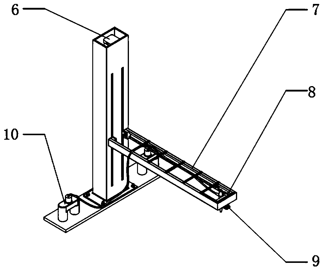
[0017] Such as figure 2 As shown, the nozzle adjustment table 1 is composed of a nozzle lifting device 6, a cantilever beam 7, a nozzle roller 8, a nozzle connecting frame 9, and a propellant tee 10; a ball screw is provided in the nozzle lifting device 6 to connect with the cantilever beam 7, and the noz...


PUM


Abstract

The invention discloses a normal-pressure spraying test table. The normal-pressure spraying test table is composed of a nozzle adjusting table, a test bed frame, a collecting table, a ball screw sliding table and an air extraction device from top to bottom in sequence; the nozzle adjusting table is fixed on the side edge of the test bed frame; the collecting table is embedded into the test bed frame, and a lead screw sliding block is arranged at the bottom of the collecting table and is connected with the ball screw sliding table; and the air extraction device is arranged below the collectingtable. According to the normal-pressure spraying test table, multidirectional movement of a nozzle in three-dimensional space can be realized, the test table is applicable to detection of different spraying injectors, and the automatic control of the spraying amount and the spraying position is realized; meanwhile, the overall structure is optimized, the splashing of liquid drops is reduced to themaximum, the liquid drop measuring precision is improved, and the experiment efficiency is improved; and in addition, the normal-pressure spraying test table is simple in structure, low in cost, convenient to install and convenient in part replacement and maintenance.

Description

technical field [0001] The invention relates to a spray device, in particular to a normal pressure spray test bench. Background technique [0002] Spray devices are widely used in the fields of agriculture, industry, medicine and aerospace. In order to obtain and evaluate the performance of spray devices, it is necessary to build a spray test bench to measure the macroscopic and microscopic characteristics of the spray by means of contact and non-contact measurement methods. , while the macroscopic parameters of the nozzle spray characteristics mainly include the atomization cone angle, the jet penetration length, the distance of liquid film breakage, and the distribution of droplets in the spray field, and the microscopic characteristic parameters include droplet size, position in the flow field, droplet Velocity, temperature, particle size distribution in the flow field. With the diversification of measurement methods and nozzle types, higher requirements are bound to be ...

Claims


Application Information

Patent Timeline
Patent Type & Authority Applications(China)
IPC IPC(8): G01M99/00G01M13/00
CPCG01M13/00G01M99/008
Inventor 陈晨赵磊何佳伟王文涛唐文献夏晶
Owner JIANGSU UNIV OF SCI & TECH
Learn More