A Method of Phase Modulating Airy Beam Trajectory Based on Parabolic Lens

An Airy beam and phase modulation technology, applied in optics, optical components, instruments, etc., can solve the problems of inability to flexibly utilize lens modulation with different focal lengths, limited lens focal length, and small offset.

An Airy beam and phase modulation technology, applied in optics, optical components, instruments, etc., can solve the problems of inability to flexibly utilize lens modulation with different focal lengths, limited lens focal length, and small offset.

CN110471188BActive Publication Date: 2021-12-14HENAN UNIV OF SCI & TECH

Image

  • A Method of Phase Modulating Airy Beam Trajectory Based on Parabolic Lens
  • A Method of Phase Modulating Airy Beam Trajectory Based on Parabolic Lens
  • A Method of Phase Modulating Airy Beam Trajectory Based on Parabolic Lens

Examples


Embodiment Construction

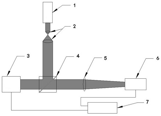
[0027] The embodiment of the present invention will be described in detail in conjunction with the accompanying drawings. This embodiment is based on the technical solution of the present invention, and provides detailed implementation and specific operation process, but the scope of protection of the present invention is not limited to the following embodiments.

[0028] According to the accompanying drawings, it can be seen that a method for phase-modulating the transmission trajectory of an Airy beam based on a parabolic lens comprises the following steps:

[0029] Step 1, emitting a Gaussian beam from a laser, and collimating and expanding the Gaussian beam;

[0030] Step 2, projecting the collimated and expanded Gaussian beam onto the beam splitter for splitting;

[0031] Step 3: inject the split beam into the spatial light modulator loaded with the phase pattern in advance, and perform phase modulation;

[0032] The phase pattern in step 4 and step 3 is to utilize compu...


PUM


Abstract

The invention provides a method for phase modulation of an Airy beam transmission trajectory based on a parabolic lens, comprising the following steps: step 1, a laser emits a Gaussian beam, and collimates and expands the Gaussian beam; Step 2, The collimated and expanded Gaussian beam is projected onto the beam splitter for splitting; step 3, inject the split beam into the spatial light modulator with the phase pattern loaded in advance, and perform phase modulation; finally, the cubic phase mask The light beam behind the membrane plate is Fourier transformed by a Fourier transform lens to obtain an Airy beam. The invention uses a computational holographic technique to obtain a phase mask of the phase factor of the parabolic lens. By changing the modulation parameters of the phase factor of the quasi-parabolic lens, the phase mask with the corresponding modulation effect is obtained, so as to realize the flexible control of the transmission trajectory of the Airy beam.

Description

technical field [0001] The invention relates to a method for regulating and controlling the transmission track of an Airy beam, and discloses a method for modulating the transmission track of an Airy beam based on the phase of a quasi-parabolic lens. Background technique [0002] In 2007, Siviloglou found that adding an exponential decay function to the Airy function can still satisfy the wave equation, and for the first time produced an Airy beam with finite energy experimentally. As a kind of non-diffracting light, Airy light has attracted great attention due to its unique properties such as approximately non-diffraction, transverse self-acceleration, and self-healing properties. The transmission trajectory of the Airy beam is parabolic rather than the conventional straight line. Since there are different requirements for the transmission trajectory of the Airy beam in different situations, the regulation of the transmission trajectory of the Airy beam has gradually becom...

Claims


Application Information

Patent Timeline
14 Dec 2021
Publication
CN110471188B
IPC
G02B27/09
CPC
G02B27/0944
Inventors
李贺贺; 张海东