Frequency agile resonant cavity antenna

A resonant cavity antenna and frequency agility technology, applied in the field of resonant cavity antennas, can solve the problems of drastic gain changes, low efficiency, and large size of resonant cavity antennas, and achieve the effects of low profile, simple feeding, and stable radiation gain

Active Publication Date: 2019-11-19
昆山荷兹天线微波技术有限公司
View PDF8 Cites 5 Cited by
  • Summary
  • Abstract
  • Description
  • Claims
  • Application Information

AI Technical Summary

Problems solved by technology

Compared with broadband resonant cavity antennas, it can effectively improve spectrum utilization and reduce filtering difficulty, and can solve the problems of large size, low efficien

Method used


Image

  • Frequency agile resonant cavity antenna
  • Frequency agile resonant cavity antenna
  • Frequency agile resonant cavity antenna

Examples


Embodiment

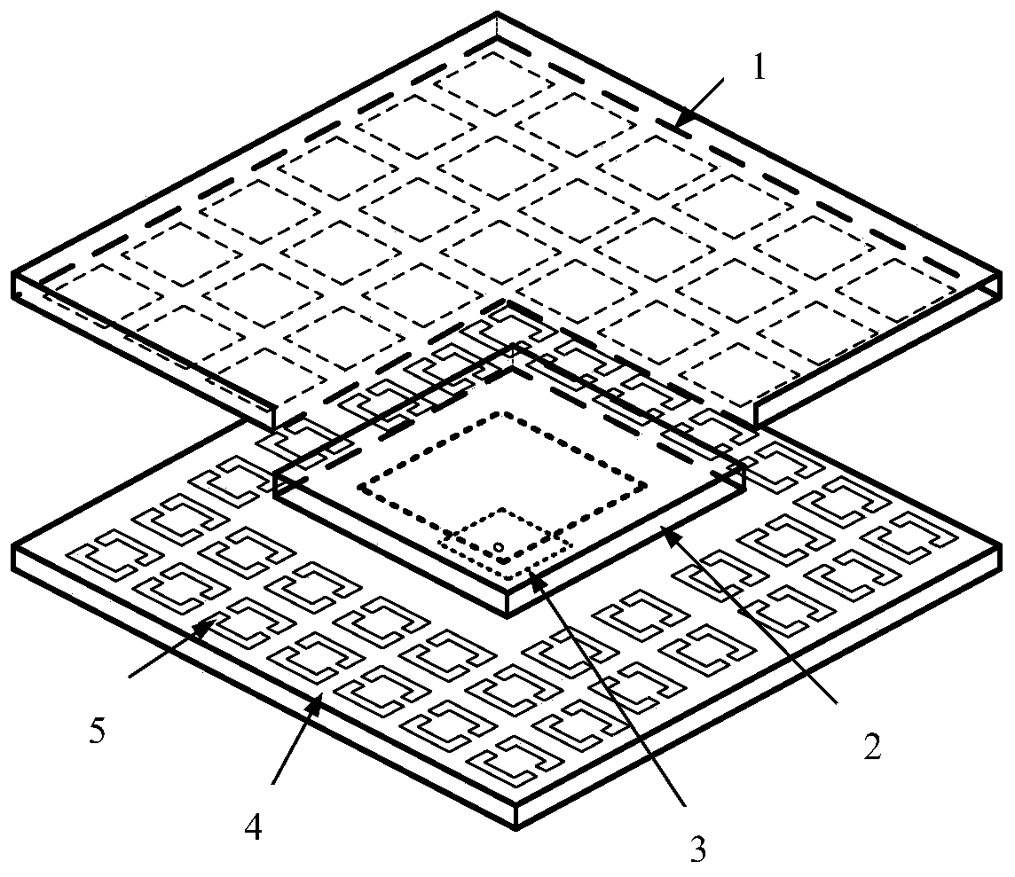
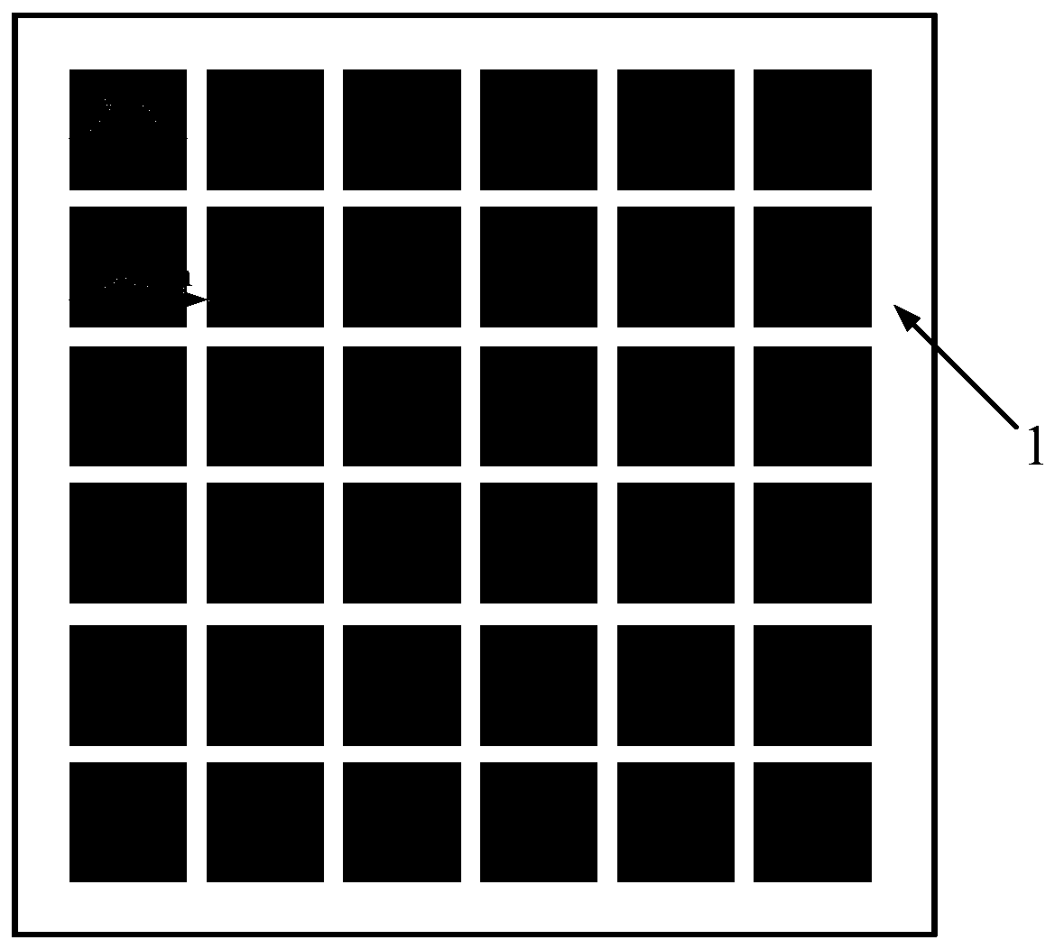
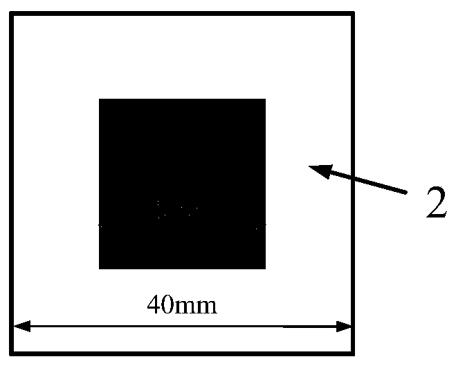
[0040] Using Rogers4003C plate with a thickness of 1.524mm and a relative dielectric constant of 3.55 as the reflective coating 1, the size is 140mm*140mm, and 6*6 square metal patch units with a side length of 19mm are printed under the dielectric plate; the thickness is 0.508 The Rogers5880 plate with a relative dielectric constant of 2.2 is used as the supporting plate of the parasitic feed, and a square parasitic patch with a side length of 16mm is printed under the dielectric plate; the Rogers4003C plate with a thickness of 1.524mm is used as the main feed and the high-impedance surface. The support plate is 140mm*140mm in size. A square patch with a side length of 13.2mm is printed in the center of the upper layer of the dielectric board, 7*7 high-impedance units and the feeder lines of the units. The lower layer of the dielectric board is a metal floor; the high-impedance unit is a metal A ring structure, slotting in the middle of the metal ring structure and loading two...


PUM

PropertyMeasurementUnit
Thicknessaaaaaaaaaa
Thicknessaaaaaaaaaa

Abstract

The invention relates to a frequency agile resonant cavity antenna. The frequency agile resonant cavity antenna comprises a main feed source, a parasitic feed source, a reflection coating, a floor anda high-impedance surface. The reflection coating is arranged on the upper portion, the floor and the high-impedance surface are arranged on the lower portion and form a cavity structure, the main feed source is printed on the high-impedance surface, and the parasitic feed source is arranged in the cavity. The reflection coating is a Rogers4003C dielectric plate, and a periodic square metal patchprinted below the dielectric plate enables the dielectric plate to have the capability of partially reflecting electromagnetic waves; the main feed source is a square patch antenna fed by a coaxial probe; the parasitic feed source is a square patch antenna printed below the dielectric plate with the dielectric constant of 2.2; the high-impedance surface is a Rogers4003C dielectric plate, and a periodic frequency agility unit is printed above the Rogers4003C dielectric plate and is used for controlling the working frequency of the resonant cavity antenna; and a metal floor structure of the resonant cavity antenna is printed on the lower surface of the Rogers4003C dielectric plate. The problems that an existing resonant cavity antenna is large in size, low in efficiency, violent in gain change and the like are solved.

Description

technical field [0001] The invention belongs to the technical field of antennas, and relates to a resonant cavity antenna, in particular to a resonant cavity antenna with frequency agility performance. Background technique [0002] A resonant cavity antenna usually consists of a feed, a floor, and a reflective coating. By placing a reflective cladding with partial reflection characteristics at an appropriate position above the feed antenna, it forms a resonant cavity structure with the antenna floor. The resonant cavity antenna overcomes the disadvantages of low gain and low efficiency of the traditional microstrip patch antenna, and can significantly increase the gain of the antenna without building an array antenna or loading a complex feed network. [0003] Since the reflection amplitude and phase of the reflective coating have frequency-selective characteristics, the resonant height of the resonant cavity is also very sensitive to changes in frequency. Usually, the work...

Claims


Application Information

Patent Timeline
IPC IPC(8): H01Q1/38H01Q1/48H01Q1/50H01Q15/14H01Q23/00H01Q5/10H01Q5/30
CPCH01Q1/38H01Q1/48H01Q1/50H01Q5/10H01Q5/30H01Q15/14H01Q23/00
Inventor 冀璐阳李建瀛张麟兮
Owner 昆山荷兹天线微波技术有限公司
Why Eureka
Try Eureka