Optical module

An optical module, input optical fiber technology, applied in the field of optical communication, can solve the problems of increasing the difficulty and complexity of the production process, limited placement position, complex production process, etc., to improve the output optical power and receiving sensitivity, flexible placement position, The effect of simplifying the assembly process

Inactive Publication Date: 2019-11-19
WUHAN ACCELINK TECH CO LTD
View PDF10 Cites 6 Cited by
  • Summary
  • Abstract
  • Description
  • Claims
  • Application Information

AI Technical Summary

Problems solved by technology

[0003] Conventional FR4 optical modules, optical devices TOSA (Transmitter Optical Subassembly, abbreviated as TOSA) / ROSA (Receiver Optical Subassembly, abbreviated as ROSA) and optical fiber output / input ports are directly coupled together, which is a hard connection. For 400G optical modules , due to the small area of ​​the coupling spot, such a structure not only makes the module structure design difficult, the production process is complicated, but also many problems will appear in the production process: (1) It is easy to cause the output optical power of the optical module to decrease and the receiving sensitivity to deteriorate , reduce the first-time yield of the module; (2) TOSA / ROSA must be coupled and debugged on the PCBA (circuit board). The coupling and debugging of PCBA and devices are serial operations, which increases the difficulty and complexity of the production process and reduces the Production efficiency; (3) Because the position of the optical port is fixed in the optical module, when the optical port and TOSA are hard-connected, the placement position of TOSA is limited, which affects the circuit layout

Method used


Image

  • Optical module
  • Optical module
  • Optical module

Examples


Embodiment 1

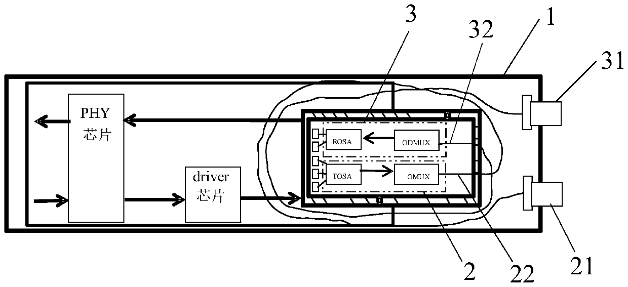
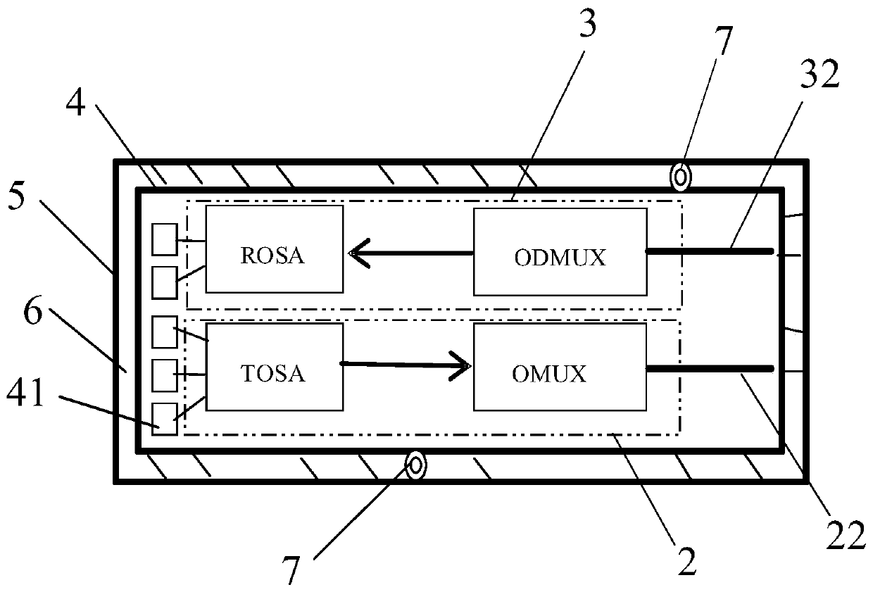
[0034] refer to figure 1 , this embodiment provides an optical module, the optical module includes: a package 1, a light emitting component 2, a light receiving component 3, a light transmitting interface 21 and a light receiving interface 31, the light transmitting component 2 and the light receiving The assembly 3 is arranged in the casing 1, the light emitting interface 21 and the light receiving interface 31 are arranged on the casing 1, the output optical fiber 22 is arranged on the side of the light emitting assembly 2, and the light receiving interface An input optical fiber 32 is provided on the module 3 side.

[0035] Wherein, the output optical fiber 22 is wound around the light emitting assembly 2 and the light receiving assembly 3, and then connected to the light emitting interface 21; the input optical fiber 32 surrounds the light emitting assembly 2 and the light receiving assembly 3. After the receiving component 3 is wound, it is connected with the light recei...


PUM


Abstract

The invention discloses an optical module. The optical module comprises a tube shell, a light emitting assembly, a light receiving assembly, a light emitting interface and a light receiving interface,the light emitting assembly and the light receiving assembly are arranged in the tube shell, the light emitting interface and the light receiving interface are arranged on the tube shell, an output optical fiber is arranged on the side of the light emitting assembly, and an input optical fiber is arranged on the side of the light receiving assembly; the output optical fiber is wound around the light emitting assembly and the light receiving assembly and then is connected with the light emitting interface; the input optical fiber is wound around the light emitting assembly and the light receiving assembly and then is connected with the light receiving interface. The light receiving assembly and the light emitting assembly are flexibly connected with the corresponding interfaces through theoptical fibers, so that the coupling difficulty is reduced, and the light receiving assembly and the light emitting assembly can be placed flexibly. Attenuation of the optical module is mainly generated by the optical fiber, attenuation generated by optical port pressure in an optical port integration scheme is avoided, attenuation can be reduced, and output optical power and receiving sensitivity are improved.

Description

technical field [0001] The invention belongs to the field of optical communication, and more specifically relates to an optical module. Background technique [0002] In recent years, 5G and data centers have been very hot topics, especially data centers. Now major large data centers around the world are about to upgrade to 400G. The 400G optical modules used in 400G data centers mainly include QSFP-DD and OSFP. According to the transmission distance, they can be divided into SR (maximum transmission distance of 100m), DR (maximum transmission distance of 500m), FR (maximum The transmission distance is 2km), LR (the maximum transmission distance is 10km); according to the number of wavelengths, it can be divided into 8 wavelengths and 4 wavelengths, among which, IEEE P802.3bs TM / D3.3 defines 400G BASE-FR8, but the mainstream of market demand is FR4. [0003] Conventional FR4 optical modules, optical devices TOSA (Transmitter Optical Subassembly, abbreviated as TOSA) / ROSA (...

Claims


Application Information

Patent Timeline
Patent Type & Authority Applications(China)
IPC IPC(8): H04B10/25H04B10/40
CPCH04B10/40
Inventor 杨俊麒胡毅王志勇张博江迪升韩燊成璇璇
Owner WUHAN ACCELINK TECH CO LTD
Why Eureka
Try Eureka