
CT-guided tumor ablation scanning positioning and ablation needle in-vitro fixator device

A scanning positioning and external fixator technology, applied in the field of medical devices, can solve the problems of affecting the curative effect, wasting manpower, and difficult to fix, and achieve the effects of avoiding serious complications, ingenious structure, and reasonable design.

Pending Publication Date: 2019-11-22
高杨
View PDF0 Cites 0 Cited by
  • Summary
  • Abstract
  • Description
  • Claims
  • Application Information

AI Technical Summary

Problems solved by technology

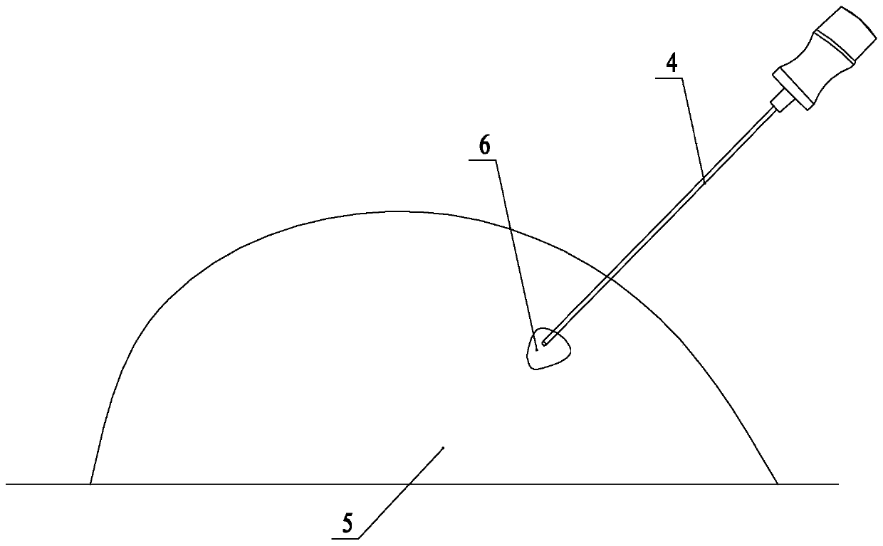
For many superficial tumors or tumors in special parts, it is difficult to fix the ablation needle 4 after it enters the body. During the ablation process, the doctor needs to support it with his hands all the time. This wastes manpower and easily leads to the angle between the needle and the body during the ablation process. If there is a change, the needle tip of the ablation needle 4 deviates from the target lesion 6, affecting the curative effect, and even if it is adjacent to important tissues such as large blood vessels, it is more likely to cause major treatment accidents
At present, there is no special ablation needle fixation device on the market. Therefore, it is necessary to design a device that integrates CT scan positioning and ablation needle external fixator to solve the above problems.

Method used


Image

  • CT-guided tumor ablation scanning positioning and ablation needle in-vitro fixator device
  • CT-guided tumor ablation scanning positioning and ablation needle in-vitro fixator device
  • CT-guided tumor ablation scanning positioning and ablation needle in-vitro fixator device

Examples


Embodiment Construction

[0023] The present invention will be further described below in conjunction with specific drawings and embodiments.

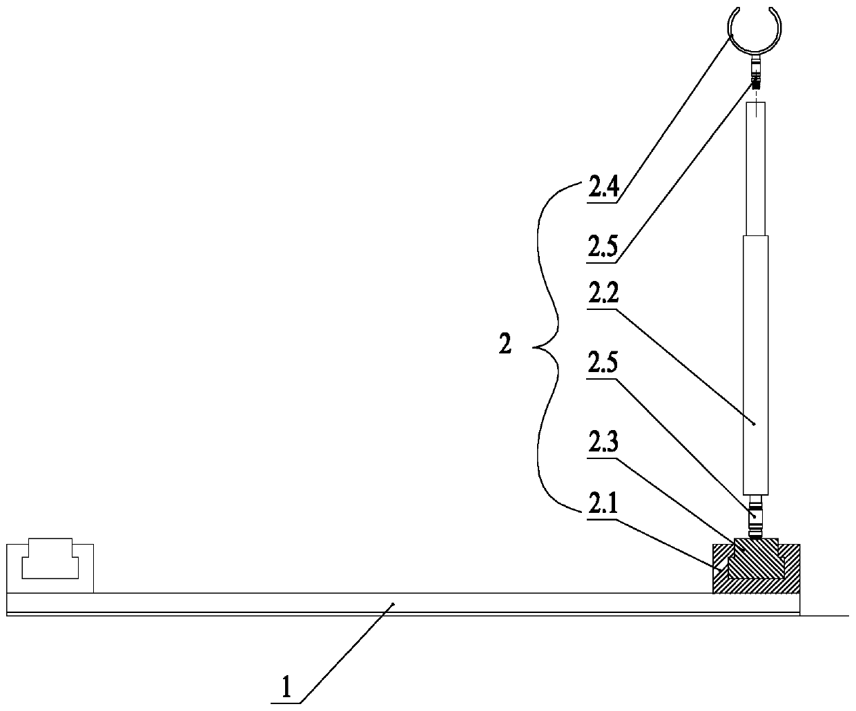
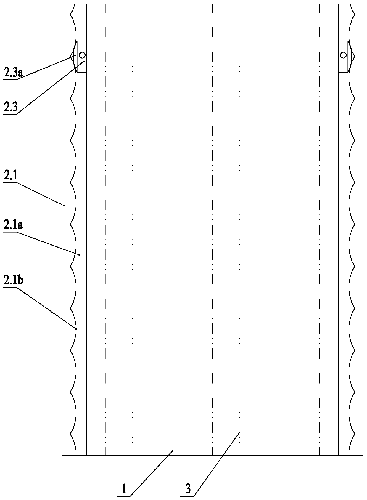
[0024] Such as figure 1 As shown, the embodiment discloses a CT-guided tumor ablation scan positioning and ablation needle external fixator device, including a transparent sticker 1 and a fixer 2, the transparent sticker 1 is rectangular, and the transparent sticker 1 is provided with There are nine evenly arranged X-ray development positioning lines 3 parallel to the direction of its long sides; at least one of the long sides of the transparent sticker 1 is provided with a fixer 2, and the fixer 2 includes a fixing seat 2.1 and a support rod 2.2, the fixed seat 2.1 is long and fixedly connected to the long side of the transparent sticker 1, the fixed seat 2.1 is provided with a sliding groove 2.1a, and the sliding block 2.3 is installed in the sliding groove 2.1a. There is frictional resistance between the slider 2.3 and the chute 2.1a; the lower end of the s...


PUM


Abstract

The invention relates to a CT-guided tumor ablation scanning positioning and ablation needle in-vitro fixator device, and is characterized in that the device includes a transparent adhesive tape and afixator; the transparent adhesive tape is rectangular, and nine X-ray development positioning lines arranged evenly parallel to a long side direction of the transparent adhesive tape are arranged onthe transparent adhesive tape; at least one long side of the transparent adhesive tape is provided with the fixator, and the fixator includes a fixed base and a support rod; the fixed base is in a long strip shape and is fixedly connected on the long side of the transparent adhesive tape, the fixed base is internally provided with a sliding groove, the sliding groove is internally provided with asliding block, and friction resistance exists between the sliding block and the sliding groove; the lower end of the support rod is connected with the sliding block, and the upper end of the support rod is provided with a caliper for holding and fixing an ablation needle. The device has the advantages of ingenious structure, reasonable design and convenient use. In the process of microwave ablation, hands of a doctor can be liberated, the displacement of the ablation needle can be prevented, and serious complications can be avoided from being caused.

Description

technical field [0001] The invention relates to a CT-guided tumor ablation scan positioning and an ablation needle external fixator device, which belongs to the technical field of medical devices. Background technique [0002] In addition to surgical resection, internal medicine chemotherapy, and external radiation therapy for tumor treatment, a minimally invasive interventional therapy commonly used at present is percutaneous imaging-guided puncture ablation therapy, which is often guided by CT. The advantages of this treatment are less trauma, less side effects, and faster postoperative recovery. It is suitable for many tumor patients who cannot tolerate surgery, and it is often combined with medical chemotherapy or targeted drug therapy. [0003] Currently commonly used ablation treatments include radiofrequency ablation, microwave ablation, and cryoablation. Mainly under the guidance of CT scanning, the needle tip of the ablation needle 4 is percutaneously punctured int...

Claims


Application Information

Patent Timeline
IPC IPC(8): A61B18/12A61B18/14A61B90/11A61B34/20
CPCA61B18/12A61B18/1402A61B34/20A61B90/11A61B2018/00577A61B2034/2065
Inventor 高杨陈骏李潇李健彬韩宜璇周士波严萍高若溪杨红徐光珍
Owner 高杨
Learn More