Laser cutting machine hydraulic lifting working platform

A laser cutting machine, hydraulic lifting technology, applied in laser welding equipment, manufacturing tools, metal processing equipment and other directions, can solve the problems of troublesome maintenance, long installation time, high cost, and achieve simple maintenance in the later stage, improve production efficiency, The effect of cost reduction

Pending Publication Date: 2019-11-22
苏州领创先进智能装备有限公司
View PDF0 Cites 1 Cited by
  • Summary
  • Abstract
  • Description
  • Claims
  • Application Information

AI Technical Summary

Problems solved by technology

Due to the high power of the laser, the high-power laser cutting machine can cut steel plates with a large area, such as the 6000×2500mm steel plate currently on the market. For thick plates, the lifting table of the high-power laser cutting machine must be able to lift, and at the same time, it must have a certain speed. However, the mechanically driven laser cutting machine lifting and exchange table currently on the market has the following three disadvantages: 1. The lifting and exchanging speed of the workbench is slow, and the exchange time is long; 2. The maximum workpiece weight that the workbench can carry is small, which cannot meet the needs of high-power laser cutting machines; 3. The structure of the mechanical transmission workbench is complex, and the installation time is long. Maintenance is troublesome and expensive
[0003] Therefore, it is difficult to meet the needs of such large-area thick plates on high-power laser cutting machines with the lifting exchange table of mechanically driven laser cutting machines currently on the market.

Method used


Image

  • Laser cutting machine hydraulic lifting working platform
  • Laser cutting machine hydraulic lifting working platform
  • Laser cutting machine hydraulic lifting working platform

Examples


Embodiment Construction

[0021] The present invention is described in detail below in conjunction with accompanying drawing and specific embodiment:

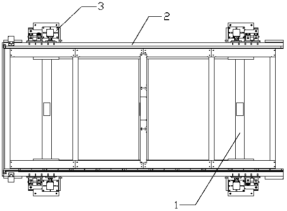
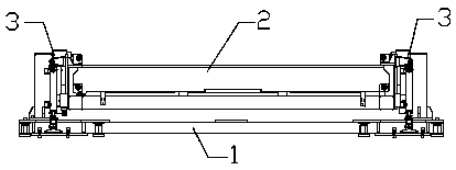
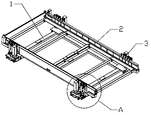
[0022] Figure 1 to Figure 3 A laser cutting machine hydraulic lifting workbench is shown, which includes a chassis 1 and a workbench 2 arranged above the chassis 1. Both the chassis 1 and the workbench 2 have a rectangular structure, and the outer sides of the chassis 1 are respectively arranged near the four corners. A base 11 extending outward, on which a hydraulic lifting device 3 capable of moving vertically up and down is arranged, the top of the hydraulic lifting device 3 is connected to the workbench 2, and four groups of hydraulic lifting devices arranged on the chassis 1 The device 3 realizes the pressure balance of the oil circuit by connecting the external synchronous hydraulic station, and drives the workbench 2 to realize vertical movement up and down.

[0023] like Figure 4 As shown, the hydraulic lifting device 3 is composed of a hydr...


PUM


Abstract

The invention discloses a laser cutting machine hydraulic lifting working platform. The laser cutting machine hydraulic lifting working platform comprises a chassis and a working platform arranged above the chassis; the chassis and the working platform are both of rectangular structures; bases extending outwards are correspondingly arranged in positions, close to the four corners, of the externalside of the chassis; hydraulic lifting devices capable of vertically moving up and down are arranged on the bases; the tops of the hydraulic lifting devices are connected with the working platform; and the four groups of hydraulic lifting devices arranged on the chassis realize oil passage pressure balance by being connected with an external synchronous hydraulic station and drives the working platform to vertically move up and down. By using a hydraulic oil cylinder as a transmission mode, the laser cutting machine hydraulic lifting working platform has the advantages that the lifting exchanging speed is high, the exchanging time is short, the performance is stable, the platform can bear a large-area thick steel plate with larger weight, the use of a large-power laser cutting machine canbe satisfied, the structure is simple, the platform is easy to mount and detach, the later maintenance is simpler, the use cost is reduced, and the production efficiency is enhanced.

Description

technical field [0001] The invention relates to the field of laser cutting, in particular to a hydraulic lifting workbench of a laser cutting machine. Background technique [0002] The laser cutting machine lifting exchange table is a device used in the field of laser cutting, which can realize fast loading and unloading of laser cutting machines. At present, most of the lifting and exchanging tables of laser cutting machines on the market use mechanical transmission. With the continuous advancement of laser cutting technology, high-power laser cutting machines have emerged as the times require. Due to the high power of the laser, the high-power laser cutting machine can cut steel plates with a large area, such as the 6000×2500mm steel plate currently on the market. For thick plates, the lifting table of the high-power laser cutting machine must be able to lift, and at the same time, it must have a certain speed. However, the mechanically driven laser cutting machine liftin...

Claims


Application Information

Patent Timeline
Patent Type & Authority Applications(China)
IPC IPC(8): B23K26/70B23K26/38
CPCB23K26/38B23K26/702
Inventor 宋维建沈晖李超
Owner 苏州领创先进智能装备有限公司
Why Eureka
Try Eureka