Steel bar welding platform for construction engineering

A welding platform and construction engineering technology, applied in welding equipment, auxiliary welding equipment, welding/cutting auxiliary equipment, etc., can solve the problems of unable to accelerate the cooling of steel bars, and cannot remove rust on the surface of steel bars, so as to achieve the effect of accelerated cooling

Pending Publication Date: 2019-11-22
中建河图建设有限公司
View PDF1 Cites 4 Cited by
  • Summary
  • Abstract
  • Description
  • Claims
  • Application Information

AI Technical Summary

Problems solved by technology

A steel bar welding positioning device in the above-mentioned patent has the following disadvantages: the steel bar can be moved to a predetermined position by the guiding mechanism, and the steel bar to be welded can be fixed by the pressing mechanism to perform steel bar welding, but it cannot adjust the welded steel bar Accelerated cooling can not remove the rust on the surface of the steel bar

Method used


Image

  • Steel bar welding platform for construction engineering
  • Steel bar welding platform for construction engineering
  • Steel bar welding platform for construction engineering

Examples


Embodiment 1

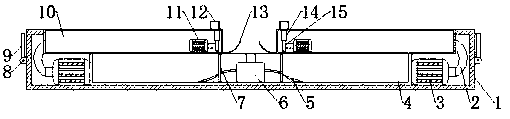
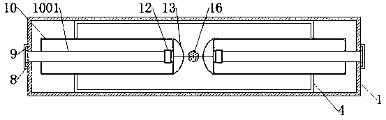
[0029] refer to Figure 1-6 , a steel bar welding platform for construction engineering, comprising a main body 1, the bottom inner wall of the main body 1 is fixedly connected with a water tank 4, the middle part of the bottom inner wall of the water tank 4 is connected with an atomizing nozzle 6 by bolts, and the top of the main body 1 is provided with a bar-shaped Through holes, the main body 1 is fixedly connected with two fixed boxes 10 at the strip-shaped through holes, the bottom inner walls of the two fixed boxes 10 are equipped with motors 11 through bolts, and the top side of the fixed boxes 10 is equipped with a second One through hole, the fixed box 10 is provided with a grinding structure at the first through hole, the grinding structure includes a fixed plate 1401, the fixed plate 1401 is fixedly connected with the fixed box 10, and one side of the fixed plate 1401 is provided with a toothed ring 14, the toothed ring A metal wire 1402 is fixedly connected to the ...

Embodiment 2

[0037] refer to Figure 7 , a steel bar welding platform for construction engineering. Compared with Embodiment 1, in this embodiment, in order to facilitate the handling and movement of the device, the bottom of the main body 1 is provided with four grooves, and the main body 1 is fixedly connected to the grooves. The second rotating shaft 17, the outer wall of the second rotating shaft 17 is fixedly connected with the rotating rod 18, and the bottom end of the rotating rod 18 is fixedly connected with the wheel 19, the rotation of the rotating rod 18 can be controlled by the second rotating shaft 17, thereby the wheel 19 can be controlled shrinkage.

[0038] When in use, first turn on the power, start the motor 11, the rotation of the motor 11 drives the gear 15 to rotate, the gear 15 drives the gear ring 14 to rotate, the gear ring 14 rotates to drive the metal wire 1402 to rotate, and the rotation of the gear ring 14 can drive the fixed cylinder 1403 to rotate , the fixed...


PUM


Abstract

The invention belongs to the technical field of construction engineering, and particularly relates to a steel bar welding platform for construction engineering. The steel bar welding platform aims tosolve the technical problem that the welding steel bar needs to be quickly cooled after rust and welding of a welding head need to be removed; the following scheme is provided, the steel bar welding platform comprises a main body, a water tank is fixedly connected to the inner wall of the bottom end of the main body, and an atomizing nozzle is fixedly arranged in the middle of the inner wall of the bottom end of the water tank; a strip-shaped through hole is formed in the top end of the main body, the main body is fixedly connected with two fixing boxes at the strip-shaped through hole, motorsare fixedly installed on one sides of the inner walls of the bottom ends of the two fixing boxes, first through holes are formed in one sides of the top ends of the fixing boxes, and grinding structures are arranged at the position of the first through holes, the and the grinding structures comprises fixing plates. According to the steel bar welding platform, the edge and the cross section of thewelding head can be ground through the grinding structures, so that the rust on the surface of the steel bar can be removed, so that the welding of the steel bar welding platform is more stable, andthe spraying can be blown upward through the blowing, so that the cooling of the welding head is accelerated.

Description

technical field [0001] The invention relates to the technical field of construction engineering, in particular to a steel bar welding platform for construction engineering. Background technique [0002] In construction projects, the use of steel bars is essential. Sometimes, during construction, longer steel bars are needed, but the existing steel bars are not long enough, which will slow down the progress of the project. We can use the two This embarrassing situation can be solved by welding together shorter steel bars, but it is necessary to remove the rust of the welding head during welding, and at the same time, it needs to be cooled quickly after welding. [0003] After searching, the Chinese patent application number is 201611184121.1, which discloses a steel bar welding positioning device, including a guiding mechanism and a pressing mechanism. A steel bar welding positioning device in the above-mentioned patent has the following disadvantages: the steel bar can be m...

Claims


Application Information

Patent Timeline
Patent Type & Authority Applications(China)
IPC IPC(8): B23K37/00B23K37/04B24B27/033
CPCB23K37/003B23K37/04B23K2103/04B24B27/033
Inventor 王凡钱光华林少龙徐盖陈子杰陈登意张敏
Owner 中建河图建设有限公司
Why Eureka
Try Eureka