
Glue spraying mechanism of hot-melting compounding machine

A composite machine and hot-melt technology, applied in the direction of layered products, lamination devices, lamination, etc., can solve the problems of conveyor belts not running normally, increasing labor intensity, reducing work efficiency, etc., to achieve convenient and fast glue removal, The effect of reducing labor intensity and improving work efficiency

Inactive Publication Date: 2019-11-22
ANHUI ZHICHENG ELECTROMECHANICAL SPARE PARTS
View PDF0 Cites 0 Cited by
  • Summary
  • Abstract
  • Description
  • Claims
  • Application Information

AI Technical Summary

Problems solved by technology

[0002] With the development of the automobile industry and the progress of automobile production and processing, automatic processing is mostly used in the processing process, and in the automobile production process, a variety of materials need to be used, among which composite materials are used more, because of its excellent characteristics are widely used, and in the production process of composite materials, multi-layer materials are usually made by hot-melt laminating machine, and each layer of materials needs to be connected by spraying glue. In the prior art, in order to ensure the uniformity of spraying glue Generally, the area covered by the nozzle will be larger than the area of ​​the material. After a long time of processing, a large amount of glue will be covered on both sides of the conveyor belt, which will cause the conveyor belt to fail to operate normally, and it is not easy to clean after the glue solidifies. It needs to stop production before cleaning. , greatly reducing work efficiency and increasing labor intensity

Method used


Image

  • Glue spraying mechanism of hot-melting compounding machine
  • Glue spraying mechanism of hot-melting compounding machine
  • Glue spraying mechanism of hot-melting compounding machine

Examples


Embodiment Construction

[0020] The following will clearly and completely describe the technical solutions in the embodiments of the present invention with reference to the accompanying drawings in the embodiments of the present invention. Obviously, the described embodiments are only some, not all, embodiments of the present invention. Based on the embodiments of the present invention, all other embodiments obtained by persons of ordinary skill in the art without making creative efforts belong to the protection scope of the present invention.

[0021] In the description of the present invention, it should be noted that the orientation or positional relationship indicated by the terms "vertical", "upper", "lower" and "horizontal" are based on the orientation or positional relationship shown in the drawings, and are only for It is convenient to describe the present invention and simplify the description, but does not indicate or imply that the device or element referred to must have a specific orientati...


PUM


Abstract

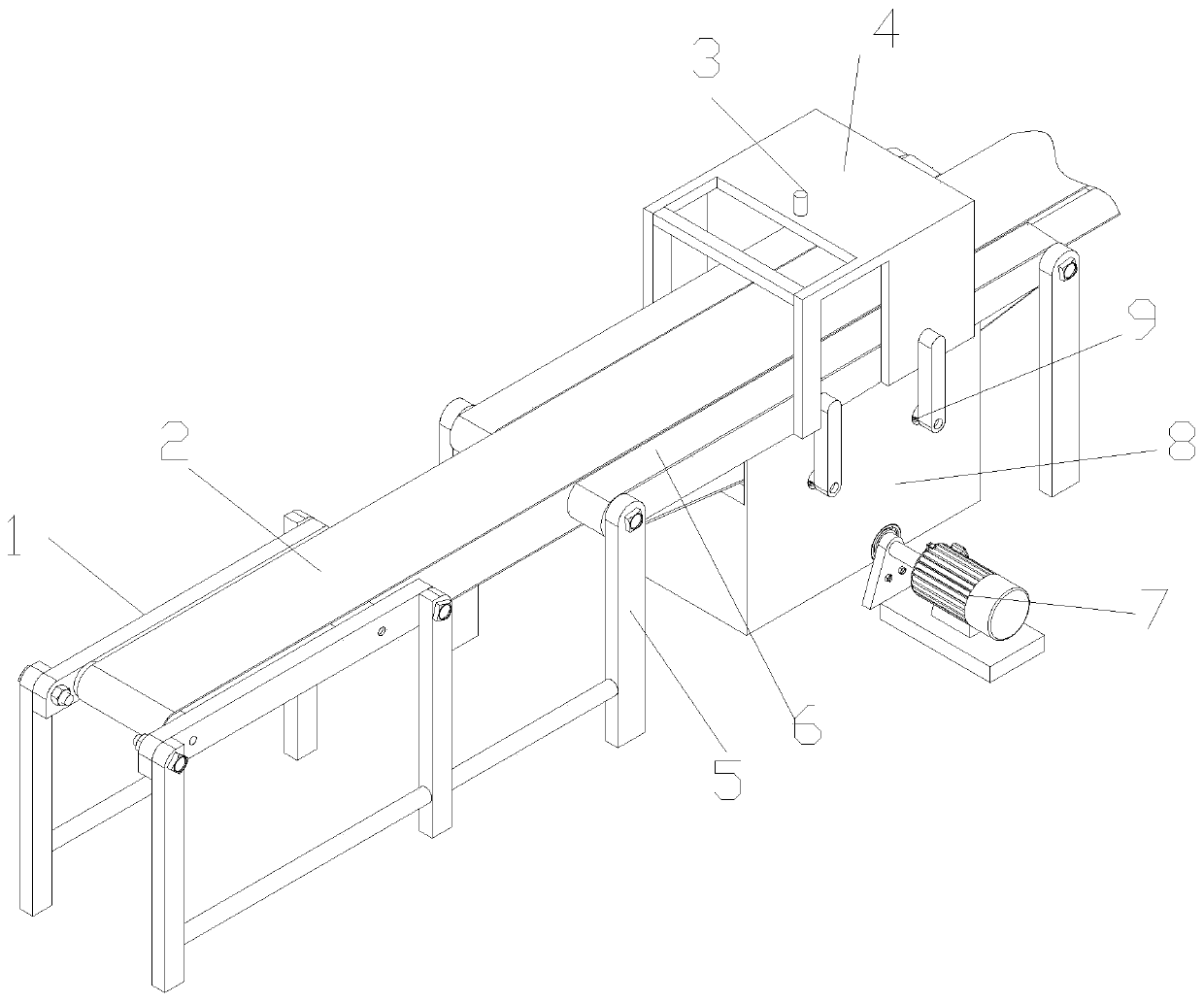
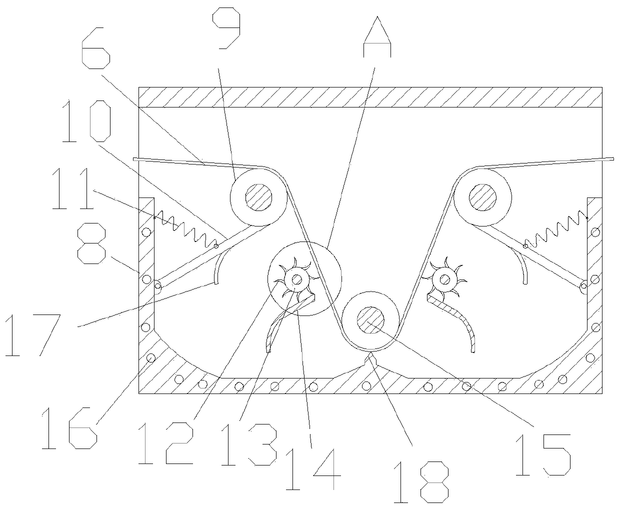
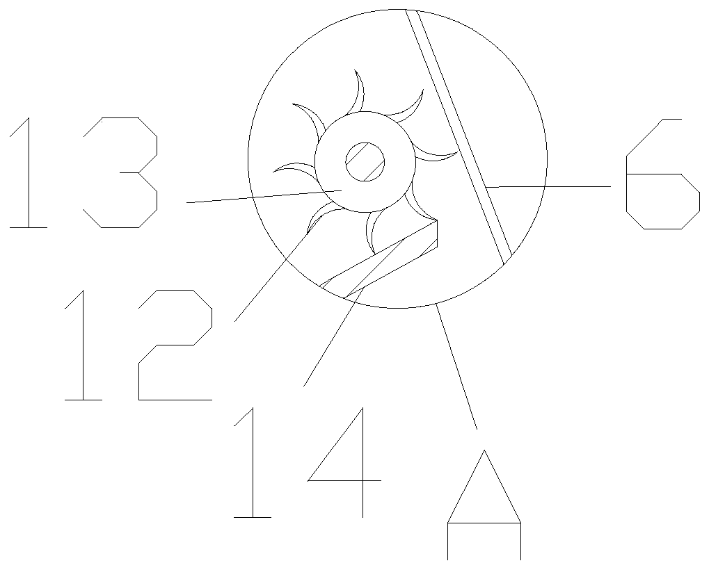
The invention discloses a glue spraying mechanism of a hot melting compounding machine. The mechanism comprises a first supporting frame, wherein a conveying belt is mounted at the upper end of the first supporting frame; a hot melting compounding machine is mounted on the conveying belt; a glue spraying head is arranged at the front end of the hot melting compounding machine; second supporting frames are arranged on the two sides of the bottom of the hot melting compounding machine; edge conveying belts are installed on the second supporting frames; the edge conveying belts are arranged on the two sides of the conveying belt; glue removing chambers are arranged at the bottom of the second supporting frames; glue removing scrapers are arranged in inner cavities of the glue removing chambers; a driving roller is arranged at the bottom of the glue removing chambers; and a first driving motor is installed on one side of the driving roller. Because the edge conveying belts are arranged onthe two sides of the conveying belt, redundant glue can be sprayed to the edge conveying belts, and scraped by the glue removing scrapers to achieve automatic glue removing, glue accumulation is prevented, normal use is achieved, glue removing is convenient and rapid, the working efficiency is improved, and the labor intensity is reduced.

Description

technical field [0001] The invention relates to the technical field of glue spraying, in particular to a glue spraying mechanism of a hot-melt compound machine. Background technique [0002] With the development of the automobile industry and the progress of automobile production and processing, automatic processing is mostly used in the processing process, and in the automobile production process, a variety of materials need to be used, among which composite materials are used more, because of its excellent characteristics are widely used, and in the production process of composite materials, multi-layer materials are usually produced by hot-melt laminating machines, and each layer of materials needs to be connected by spraying glue. In the prior art, in order to ensure the uniformity of spraying glue Generally, the area covered by the nozzle will be larger than the area of ​​the material. After long-term processing, a large amount of glue will be covered on both sides of t...

Claims


Application Information

Patent Timeline
Patent Type & Authority Applications(China)
IPC IPC(8): B32B37/12B32B37/06
CPCB32B37/06B32B37/1207B32B37/1284B32B2037/1215
Inventor 方举何斌段启松黄林刘祖俊
Owner ANHUI ZHICHENG ELECTROMECHANICAL SPARE PARTS
Learn More