Load control circuit, load control module and electrical control box
A load control and control module technology, applied in the fields of electrical control boxes, load control modules, and load control circuits, can solve problems such as inability to adjust at will, reduce device maintenance times, facilitate maintenance and replacement, and reduce work stability and life. the effect of
- Summary
- Abstract
- Description
- Claims
- Application Information
AI Technical Summary
Problems solved by technology
Method used
Image

Examples
Embodiment 1
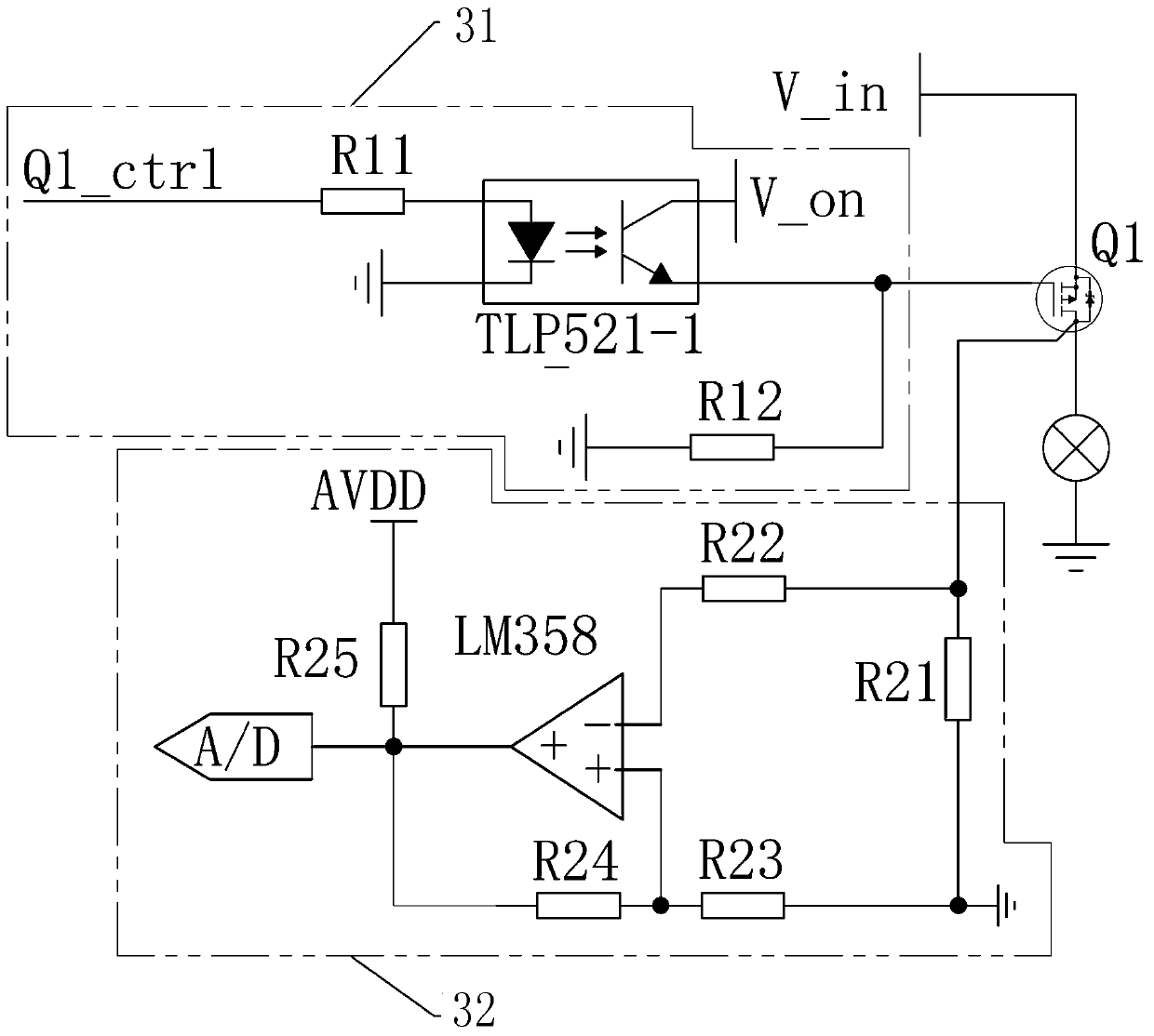
[0041] Embodiment 1: a kind of load control circuit, see Figure 2-3 , including a current power switch Q1, a current detection module 32 and a control module 31, the current detection module 32 is used to detect the load terminal current of the current power switch Q1, and outputs a first signal related to the load terminal current, and the control module 31 is used to receive The first signal; when the load terminal of the current power switch Q1 needs to be disconnected, the control module 31 outputs a second signal, and the control terminal of the current power switch Q1 responds to the second signal, so that the load terminal of the current power switch Q1 is disconnected, and the current power supply The load terminal of the switch Q1 needs to be disconnected, including the situation that the load terminal current corresponding to the first signal is greater than or equal to the set cut-off current, and also includes other situations where the load terminal needs to be di...
Embodiment 2
[0046] Embodiment 2: a load control module, see Figure 4-5 , including a control switch assembly 20 and a control module assembly 21.
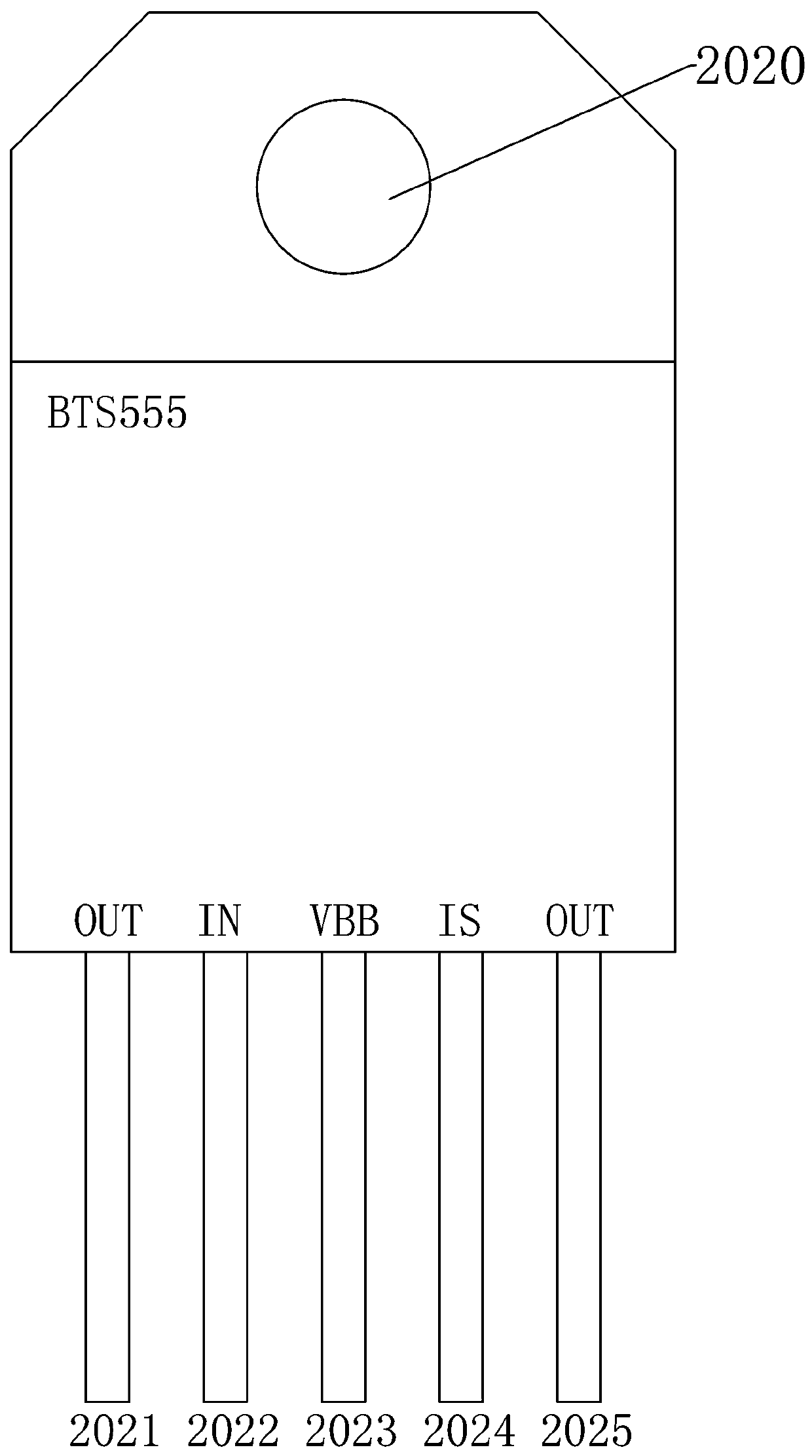
[0047] The control switch assembly 20 includes a control switch base, a current power switch 202, the control switch base includes a load input conductive bar 2012 and a load output conductive bar 2013, and the current power switch 202 includes a load input pin 2023, a load output pin 2021, a load input pin 2023, and a load output pin 2021. The output pin 2025, the control input pin 2022 and the signal output pin 2024 related to the load terminal current, the load input pin 2023 is electrically connected to the load input conductive bar 2012, and the load output pin 2021 is electrically connected to the load output pin 2025. connected, and electrically connected to the load output conductive bar 2014. In this embodiment, the current power switch 202 is fixed on the load input conductive bar 2012 , specifically, the fixing hole 2020 of the cu...
Embodiment 3
[0055] Embodiment 3: a load control module, see Figure 6-7 , including a control switch assembly 20 and a control module assembly 21. As a further improvement to Embodiment 1, the following technical features are added in this embodiment:
[0056] Further, see Figure 7 , the first insulating seat 2011 includes a connector installation hole 20114, the control module base also includes a connector 2015, the pin 20151 of the connector 2015 is electrically connected to the load output conductive bar 2014, and the connector 2015 is installed in the connector installation hole 20114 .
[0057] Further, see Figure 8 The base of the control switch further includes a first insulating seat 2011 , the base of the control module further includes a second insulating seat 2111 , the second insulating seat 2111 is a casing, and the first insulating seat 2011 and the second insulating seat 2111 are hermetically connected.
PUM
 Abstract
Description
Claims
Application Information
 - R&D
- Intellectual Property
- Life Sciences
- Materials
- Tech Scout
- Unparalleled Data Quality
- Higher Quality Content
- 60% Fewer Hallucinations
Browse by: Latest US Patents, China's latest patents, Technical Efficacy Thesaurus, Application Domain, Technology Topic, Popular Technical Reports.
© 2025 PatSnap. All rights reserved.Legal|Privacy policy|Modern Slavery Act Transparency Statement|Sitemap|About US| Contact US: help@patsnap.com