Electrolytic flotation device for wastewater treatment

An electrolytic air flotation and wastewater treatment technology, which is applied in water/sewage treatment equipment, water/sewage treatment, flotation water/sewage treatment, etc., can solve the problem of hydrogen bubble activity and limited range of action, reduce the amount of bubbles around the electrode, Reduce the practicability of the electrolytic air flotation device to achieve the effect of preventing signal overflow, increasing the range of activities, and improving practicability

Inactive Publication Date: 2019-11-22
江苏润寅石墨烯科技有限公司
View PDF0 Cites 2 Cited by
  • Summary
  • Abstract
  • Description
  • Claims
  • Application Information

AI Technical Summary

Problems solved by technology

[0003] However, during the operation of the existing electrolytic air flotation device, since the position of the electrode remains unchanged, and the hydrogen bubbles are mainly generated near the cathode, the activity and action range of the hydrogen bubbles are limited, and the bubbles mainly act on the sewage around the cathode. , and for the sewage in other locations, due to the long distance, the purification range is limited. Not only that, in the process of electrolysis, the surface of the electrode is easy to scale, which affects the contact between the electrode and the sewage, which not only increases the power consumption, but also reduces The generation of air bubbles around the electrodes reduces the practicability of existing electrolytic air flotation devices

Method used


Image

  • Electrolytic flotation device for wastewater treatment
  • Electrolytic flotation device for wastewater treatment
  • Electrolytic flotation device for wastewater treatment

Examples


Embodiment Construction

[0028] The present invention is described in further detail now in conjunction with accompanying drawing. These drawings are all simplified schematic diagrams, which only illustrate the basic structure of the present invention in a schematic manner, so they only show the configurations related to the present invention.

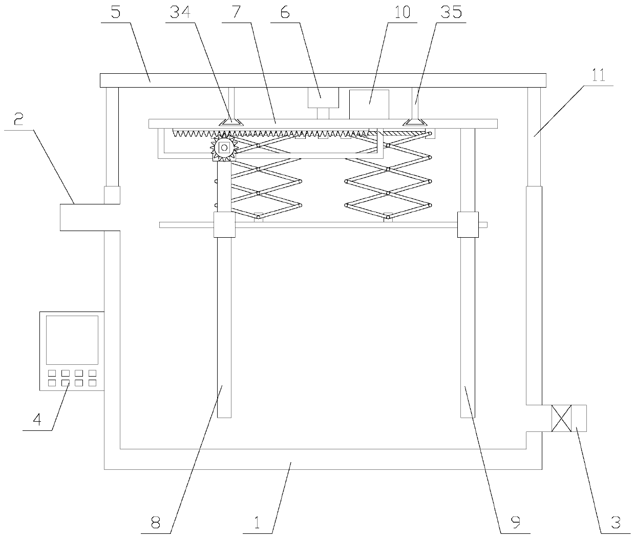
[0029] Such asfigure 1 As shown, an electrolytic air flotation device for wastewater treatment includes a pool 1, a water inlet pipe 2, a drain pipe 3, a controller 4, a top cover 5, a first motor 6, a disk 7, a cathode 8, an anode 9, A moving mechanism, a cleaning mechanism, a storage battery 10 and two support rods 11, the water inlet pipe 2 and the drain pipe 3 are respectively arranged on both sides of the pool 1, and the water inlet pipe 2 and the drain pipe 3 are all communicated with the pool 1. The drain pipe 3 is provided with a valve, the controller 4 is fixed on the pool 1, the controller 4 is provided with a PLC, and the two support rods 11 are res...


PUM


Abstract

The invention relates to an electrolysis flotation device for wastewater treatment. The device comprises a pool, a first motor, a disc, a cathode, an anode, a moving mechanism and a cleaning mechanism, wherein the moving mechanism comprises a translation plate, a second motor and two moving assemblies. The cleaning mechanism comprises a lifting assembly, a lifting table and two circular rings. Themoving assembly comprises a rotating shaft, a gear, a rack and a limiting unit; an inner ring, a plurality of cleaning brushes and a plurality of telescopic units are arranged on the inner side of the circular ring, According to the electrolysis flotation equipment for wastewater treatment, the cathode is driven to rotate through the first motor; the cathode is moved through the moving mechanism,so that the moving range of the hydrogen bubbles is enlarged, the purification range of the equipment is expanded, dirt on the surfaces of the cathode and the anode is removed through the cleaning mechanism, the cathode and the anode can be in full contact with wastewater, the electrolytic reaction rate is guaranteed, and the practicability of the equipment is improved.

Description

technical field [0001] The invention relates to the field of water purification equipment, in particular to an electrolytic air flotation equipment used for wastewater treatment. Background technique [0002] Electrolytic air flotation refers to the introduction of direct current into the sewage, and a large number of tiny hydrogen bubbles with a diameter between 18 and 90 microns are generated on the surface of the cathode in the sewage. The hydrogen bubbles adhere to the small suspended particles in the wastewater, forming an overall density smaller than water. The "bubble particle" complex, the suspended particles float to the water surface together with the air bubbles, forming foam scum, so that the suspended solids in the water can be separated, a water treatment method, because the electrolytic air flotation has simple equipment, convenient management, and resource saving , good effect, etc., the electrolytic air flotation device is an ideal substitute for the traditi...

Claims


Application Information

Patent Timeline
Patent Type & Authority Applications(China)
IPC IPC(8): C02F1/465C02F1/461
CPCC02F1/46104C02F1/465C02F2201/46105C02F2303/14
Inventor 沈智丁家伟
Owner 江苏润寅石墨烯科技有限公司
Why Eureka
Try Eureka