Landfill type bridge expansion device and construction method

A telescopic device and bridge technology, applied in bridges, bridge parts, bridge construction, etc., can solve problems such as poor stability, and achieve the effects of easy construction, excellent stretching performance, and good bonding performance

Pending Publication Date: 2019-11-22
河南聚研材料科技有限公司
View PDF0 Cites 1 Cited by
  • Summary
  • Abstract
  • Description
  • Claims
  • Application Information

AI Technical Summary

Problems solved by technology

[0003] In order to solve the problem that the existing bridge expansion device is exposed to the outside for a long time and has poor stability when driving, the p

Method used


Image

  • Landfill type bridge expansion device and construction method
  • Landfill type bridge expansion device and construction method
  • Landfill type bridge expansion device and construction method

Examples


Embodiment 1

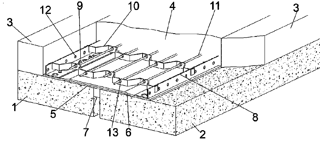
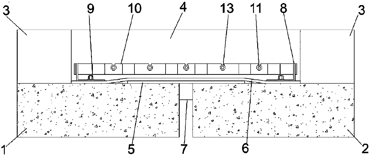
[0042] A kind of buried bridge expansion device, its structure is as follows Figure 1-Figure 6 As shown, it includes the stressed skeleton, which includes the tension and compression steel plate group matched with the expansion joint, and also includes the transverse steel bar group matched with the tension and compression steel plate group; one end of the tension and compression steel plate group is connected with the bridge 1, The other end is connected to the back wall 2; the stressed skeleton is filled with polymer concrete 4, and the polymer concrete 4 is aligned with the pavement; the expansion joint is provided with a composite plate group matched with the stressed skeleton. A sealing strip 7 is provided in the expansion joint between the bridge 1 and the back wall 2 .

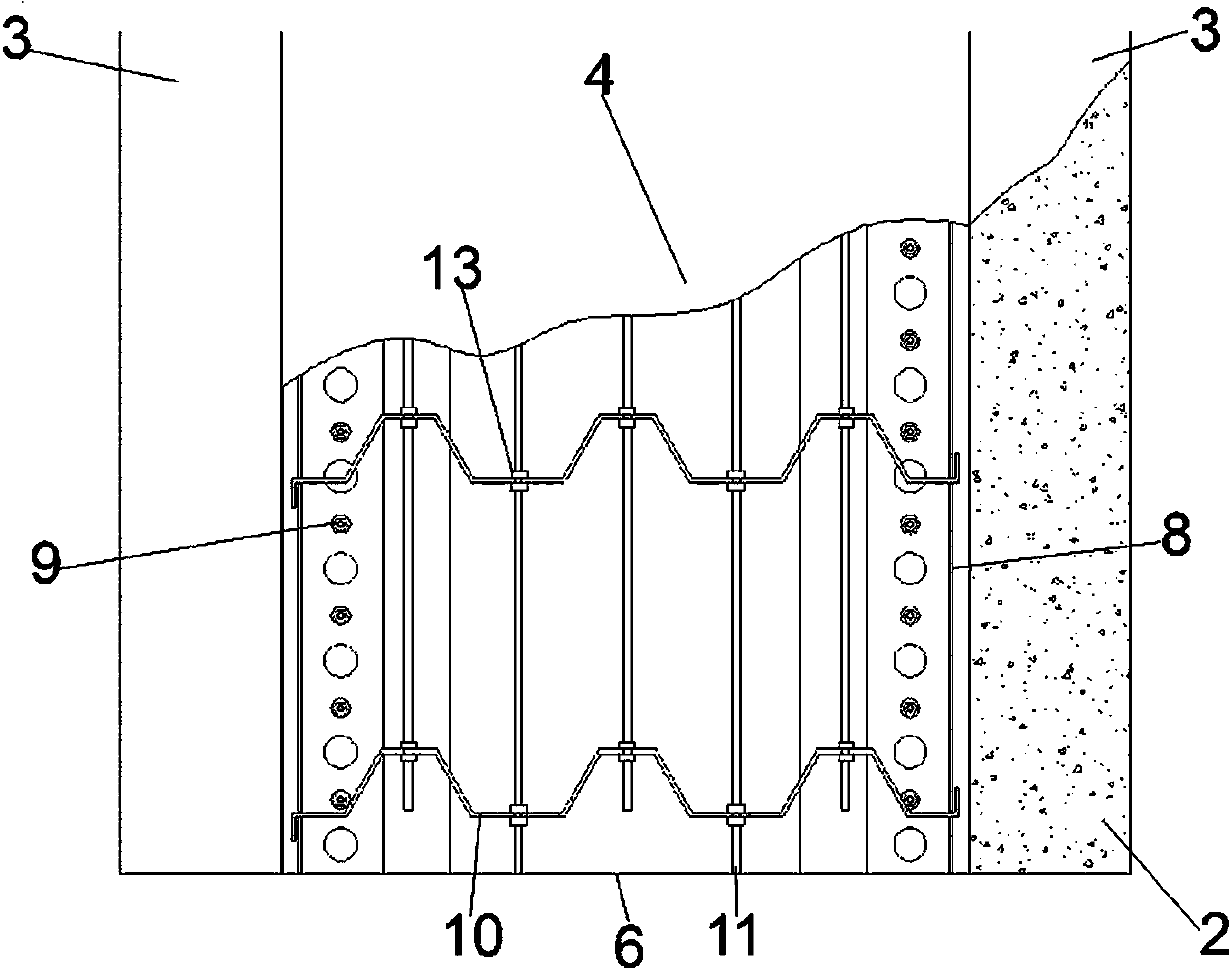
[0043] The tensile and compression steel plate group includes a plurality of corrugated steel plates 10 perpendicular to the expansion joints, and the distance between adjacent corrugated steel plates ...

Embodiment 2

[0048] A buried bridge telescopic device, which is different from Embodiment 1 in that no grout hole 12 is provided on the side of the angle steel 8 .

[0049] (1) When newly installing the landfill bridge expansion device, (a) prefabricate; weave the force-bearing skeleton, fix the transverse reinforcement group on the tensile and compression steel plate group, and the transverse reinforcement passes through the corrugated steel plates with an average interval of 30cm-50cm U-shaped notch 101 on 10 utilizes a pair of fixing nuts 13 that are all provided with at the intersection of transverse reinforcing bar 11 and any U-shaped notch 101 to fix transverse reinforcing bar 11 and corrugated steel plate 10, and a pair of fixing nuts 13 moves to Both sides of U-shaped notch 101, make the both sides of U-shaped notch 101 respectively have a fixed nut 13, rotate fixed nut 13, fixed nut 13 realizes the clamping of U-shaped notch 101 by the screw thread on the transverse steel bar 11 f...


PUM


Abstract

The invention belongs to the technical field of construction engineering, and particularly discloses a landfill type bridge expansion device and a construction method, the landfill type bridge expansion device comprises a stress framework, the stress framework comprises a tension and compression resistant steel plate group matched with an expansion joint, and further comprises a transverse steel bar group matched with the tension and compression resistant steel plate group; one end of the tensile and compression steel plate group is connected with the bridge, and the other end is connected with the back wall; the stress framework is filled with polymer concrete, and the polymer concrete is aligned with the pavement; the expansion joint is provided with a composite board set matched with the stress framework. Connection of the bridge expansion joint is achieved by arranging the stress framework, the device can be prevented from making direct contact with a vehicle through the landfill type design, the effect of driving comfort can be effectively achieved, the device can be prevented from making contact with external air, moisture and the like, and the service life of the device is prolonged.

Description

technical field [0001] The invention belongs to the field of construction engineering, and in particular relates to a buried bridge expansion device and a construction method. Background technique [0002] The bridge expansion device is a key part of the bridge component and plays an important role in realizing the bridge function. It is to meet the deformation requirements of the bridge deck and is usually installed between two bridge sections, between the bridge and the back wall (abutment) 1. Set expansion joints on the expansion joints between bridge hinge positions. Most of the existing bridge telescopic devices are directly exposed, and due to long-term exposure to air, dust, sundries and debris, automobile exhaust and acid rain, they are gradually damaged and their service life is reduced. At the same time, since it cannot be on the same plane as the road pavement, it is likely to have a serious impact on the safety and stability of the bridge expansion device due to...

Claims


Application Information

Patent Timeline
IPC IPC(8): E01D19/06
CPCE01D19/06E01D19/065
Inventor 黄正强李海勇唐寄强张建勋牛文利赵谙笛钟娟张新华
Owner 河南聚研材料科技有限公司
Why Eureka
Try Eureka