Concrete pouring system and pouring method for concrete filled steel tube bracket

A technology of steel pipe concrete and concrete, which is applied in the direction of earthwork drilling, pipe elements, pipes/pipe joints/fittings, etc., and can solve problems such as unsmoothness, support arch void, uneven and dense concrete pouring construction, etc., and achieve easy Effects of operation, improving load-carrying capacity, increasing fluidity and compactness

Pending Publication Date: 2019-11-22
SHANDONG JIANZHU UNIV
View PDF6 Cites 3 Cited by
  • Summary
  • Abstract
  • Description
  • Claims
  • Application Information

AI Technical Summary

Problems solved by technology

In order to solve the technical defects in the existing concrete pouring in the support, and to deal with the problems in the pouring, such as the emptying of the support vault, uneven and dense concrete, and unsmooth pouring construction, a set of suitable steel pipe concrete support is proposed. The concrete pouring system and its pouring method are used to ensure that the concrete in the steel pipe concrete support is filled and dense, so that the support can reach the design bearing capacity and long-term stability under the action of deep well soft rock and dynamic pressure

Method used


Image

  • Concrete pouring system and pouring method for concrete filled steel tube bracket
  • Concrete pouring system and pouring method for concrete filled steel tube bracket
  • Concrete pouring system and pouring method for concrete filled steel tube bracket

Examples


Embodiment 1

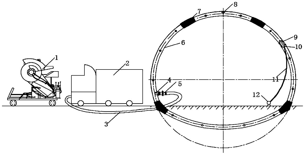
[0034] A concrete grouting system for a steel pipe concrete support, including a mixer, a delivery pump, a delivery pipeline, a check valve, an attached wind vibrator, and matching designed pouring holes and exhaust and grout holes on the support. At the bottom of one side, the exhaust and slurry discharge hole is located at the top of the bracket, the steel pipe on the side without the filling hole is connected with an attached pneumatic vibrator, and the delivery pump is connected to the filling hole through a delivery pipeline. The mixer mixes the concrete and transports the concrete to the delivery pump. The delivery pump is connected to the pouring hole through the delivery pipeline, and the concrete is poured into the steel pipe by pumping.

[0035] Concrete-filled steel tube brackets are composed of steel tubes and concrete, and are used for underground engineering support. Generally, there are various cross-sections such as straight wall semi-circular arches, shallow bo...

Embodiment 2

[0045] like Figure 5 shown.

[0046] (1) Put the concrete delivery pump flat on the roadway, and connect it to the pouring hole of the bracket through the delivery pipe.

[0047] (2) First, a group of personnel connects the cables and arranges the water pipes, and the delivery pump is empty for 15 to 20 minutes; another group of personnel goes to the stockyard to mix dry concrete, one mine car each time.

[0048] (3) Put the dry material into the mixer, add water, and mix the concrete with the mixer. The strength grade of the prepared concrete should reach C40. Add cement, sand, stones and admixtures strictly according to the ratio of C40. Take the on-site materials for trial mixing, simulate the internal environment of the steel pipe to maintain the concrete test block, fine-tune the mix ratio according to the concrete strength test results, and add the early strength agent, water reducing agent and FRP limiter to the concrete mixing according to a certain ratio. The conc...


PUM

PropertyMeasurementUnit
lengthaaaaaaaaaa
heightaaaaaaaaaa
slumpaaaaaaaaaa

Abstract

The invention relates to a concrete pouring system and pouring method for a concrete filled steel tube bracket.The concrete pouring system comprises a mixer, a delivery pump, a delivery pipeline, a check valve, a pouring hole and an exhaust slurry discharging hole matched withthe bracket andan attached pneumatic vibrator, concrete is prepared by the mixer, and delivered to the delivery pump, and the pouring hole is formed in the bracket, the pouring hole is located at the bottom end of one side of the bracket, the upper end of the other side of the bracket is connected with the attached pneumatic vibrator, the top end of the bracket is provided with theexhaust slurry discharging hole, and the delivery pump is connected with the pouring hole through the delivery pipeline. The concrete in the bracket first flows down from the pouring hole to an underground pipeline, after the concrete is filled,the concrete is poured into a pipeline above the pouring hole by pumping and jacking,when reaching the position of the exhaust slurry discharging hole of the bracket, the concrete is dropped at a high level,at the same time, the attached pneumatic vibrator drives the bracket to vibrate,and smooth and dense pouring of the concrete in the bracket is ensured. Bubbles and bleeding in the concrete in the bracket are avoided, density of the concrete is improved, and the fact that the concrete-filled steel tube bracket reaches the design bearing capacity is ensured.

Description

technical field [0001] The invention belongs to the technical field of underground engineering support, and in particular relates to a concrete pouring system and a pouring method for steel pipe concrete supports. Background technique [0002] The information disclosed in this background section is only intended to increase the understanding of the general background of the present invention, and is not necessarily taken as an acknowledgment or any form of suggestion that the information constitutes the prior art already known to those skilled in the art. [0003] With the rapid development of my country's underground engineering construction, the construction of highway and railway tunnels, subways, coal mine roadways, etc. is becoming more and more extensive. Such problems have seriously affected the safe construction of underground projects in our country, which may cause support failure. The concrete-filled steel tube support has high bearing capacity and simple construc...

Claims


Application Information

Patent Timeline
Patent Type & Authority Applications(China)
IPC IPC(8): E21D11/10F16L55/115
CPCE21D11/10E21D11/105F16L55/115
Inventor 王军杨光宋建新丁厚刚王靓
Owner SHANDONG JIANZHU UNIV
Why Eureka
Try Eureka