Fresh air system exhaust device with purification function for traffic tunnel

A technology for a fresh air system and an exhaust device, which is applied to ventilation systems, household appliances, cleaning methods and appliances, etc., can solve the problems of reduced purification capacity, reduced practicability of exhaust devices, low temperature of three-way catalytic converters, etc. The effect of purification ability, improved usability, and easy access

Inactive Publication Date: 2019-11-22
深圳市俊达通办公智能科技有限公司
View PDF8 Cites 0 Cited by
  • Summary
  • Abstract
  • Description
  • Claims
  • Application Information

AI Technical Summary

Problems solved by technology

[0003] However, when the existing fresh air system is used inside the underground traffic tunnel, the exhaust device directly discharges the air in the tunnel to the external atmosphere, and because a large amount of carbon monoxide, hydrocarbons and nitrogen oxides will be discharged during the driving process of the car inside the tunnel When these substances are directly discharged into the external environment with the exhaust device, they will pollute the atmospheric environment. A three-way catalytic converter will be added to some exhaust devices to catalyze the exhaust gas in the automobile exhaust to make carbon monoxide and hydrocarbons and nitrogen oxides into carbon dioxide, water and nitrogen that are harmless to the atmosphere, but when the catalytic reaction is carried out, the temperature of the three-way catalytic converter is low, and the catalytic ability of the three-way catalytic converter is extremely weak at low temperatures, and the exhaust gas After long-term operation of the device, the three-way catalytic converter is easily blocked by carbon deposits, resulting in a decrease in purification capacity and affecting the quality of the air discharged from the exhaust device, thereby reducing the practicability of the existing exhaust device

Method used


Image

  • Fresh air system exhaust device with purification function for traffic tunnel
  • Fresh air system exhaust device with purification function for traffic tunnel
  • Fresh air system exhaust device with purification function for traffic tunnel

Examples


Embodiment Construction

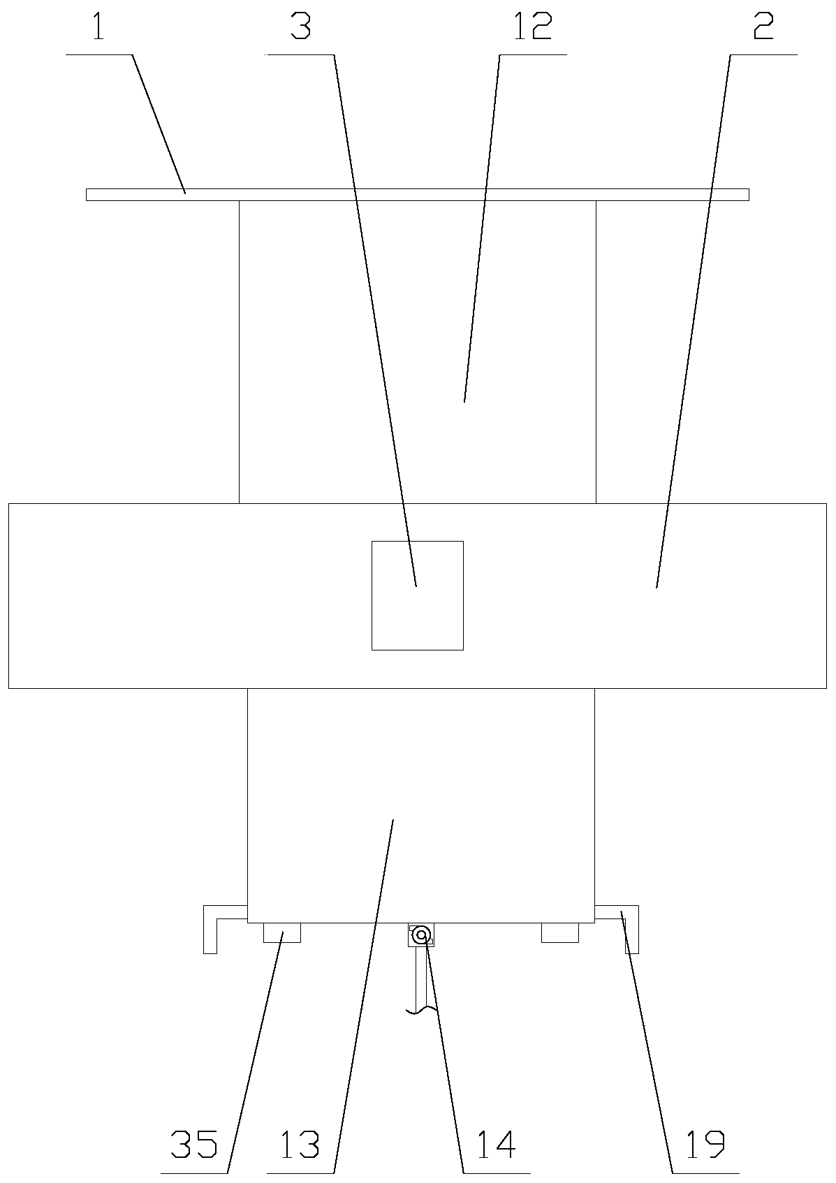
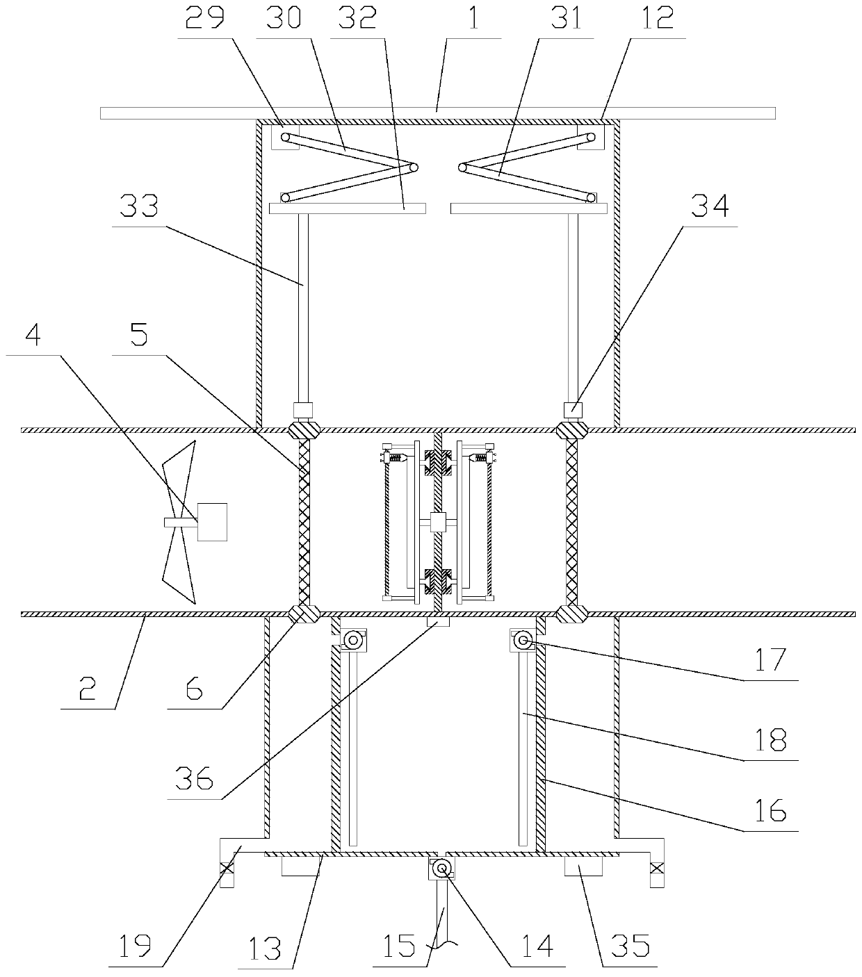
[0024] The present invention is described in further detail now in conjunction with accompanying drawing. These drawings are all simplified schematic diagrams, which only illustrate the basic structure of the present invention in a schematic manner, so they only show the configurations related to the present invention.

[0025] Such as Figure 1-2 As shown, a fresh air system exhaust device with purification function for traffic tunnels includes a roof 1, an exhaust pipe 2, a processor 3 and a cleaning mechanism. The exhaust pipe 2 is arranged under the roof 1, so The processor 3 is fixed on the exhaust pipe 2, and the processor 3 is provided with an antenna and PLC, and the exhaust pipe 2 is provided with a fan 4, a heating mechanism and two catalytic nets 5, and the fan 4 is connected to the exhaust pipe 2. The PLC is electrically connected, the heating mechanism is located between two catalytic nets 5, the outer periphery of the catalytic net 5 is provided with a frame 6, ...


PUM


Abstract

The invention relates to a fresh air system exhaust device with a purification function for a traffic tunnel. The fresh air system exhaust device comprises a top plate, an exhaust pipe, a disposer anda cleaning mechanism, wherein a fan, a heating mechanism and two catalytic nets are arranged in the exhaust pipe; the heating mechanism comprises a fixed plate, a first motor and two heating assemblies; each heating assembly comprises a rotating plate, an infrared lamp tube, a translation block, a wiping unit and two translation units; and the cleaning mechanism comprises a driving chamber, a soaking chamber, a water suction pump, a water pumping pipe, two soaking assemblies and two lifting assemblies. According to the fresh air system exhaust device with the purification function for the traffic tunnel, the uniform radiation infrared rays of the catalytic nets can be heated through the heating mechanism, so that the catalytic capacity of the catalytic nets is enhanced at a high temperature, the waste gas is converted into carbon dioxide, water and nitrogen, and the air is purified; and moreover, the carbon deposit on the catalytic nets is removed through the cleaning mechanism, so that the catalytic nets make full contact with the air conveniently, the purification capacity is enhanced, and the practicability of the device is improved.

Description

technical field [0001] The invention relates to the field of fresh air systems, in particular to an exhaust device for a fresh air system with purification function used in traffic tunnels. Background technique [0002] The fresh air system is based on sending fresh air to the room with special equipment on one side of the closed room, and then exhausting it from the other side to the outside by special equipment. A "fresh air flow field" will be formed indoors to meet the needs of indoor fresh air ventilation. The plan is: use the wind pressure, large flow fan, remove the mechanical force to send air to the room from one side, and use a specially designed exhaust fan to exhaust the room from the other side to force the formation of a fresh air flow field in the system. [0003] However, when the existing fresh air system is used inside the underground traffic tunnel, the exhaust device directly discharges the air in the tunnel to the external atmosphere, and because a large...

Claims


Application Information

Patent Timeline
IPC IPC(8): F24F7/06F24H3/04B08B1/00B08B3/12B01D53/86
CPCF24F7/06F24H3/0405B08B3/12B01D53/86B08B1/143
Inventor 刘金生
Owner 深圳市俊达通办公智能科技有限公司
Why Eureka
Try Eureka