
Lidar device and mobile robot

A technology of laser radar and adjustment device, applied in the direction of measuring device, instrument, manipulator, etc., can solve the problems of unfavorable batch manufacturing and production, increase the cost of laser radar, etc., achieve a wide scanning range, overcome a small scanning range, and reduce manufacturing. cost effect

Pending Publication Date: 2019-11-22
SHENZHEN SILVER STAR INTELLIGENT TECH CO LTD
View PDF0 Cites 11 Cited by
  • Summary
  • Abstract
  • Description
  • Claims
  • Application Information

AI Technical Summary

Problems solved by technology

However, when the environment of the mobile robot changes or the size of the obstacle is large, the laser radar can only scan and obtain a part of the information of the obstacle. This incomplete information will limit the mapping, navigation and walking of the mobile robot. Some Manufacturers propose multi-line lidar, that is, lidar with multiple emitters. By increasing the number of emitters, the scanning range of lidar is increased to realize the scanning of three-dimensional space environment. However, this method will inevitably increase the laser The cost of radar is not conducive to mass manufacturing and production

Method used


Image

  • Lidar device and mobile robot
  • Lidar device and mobile robot
  • Lidar device and mobile robot

Examples


Embodiment Construction

[0028] In order to make the technical problems, technical solutions and beneficial effects solved by the present invention clearer, the present invention will be further described in detail below in conjunction with the accompanying drawings and embodiments. It should be understood that the specific embodiments described here are only used to explain the present invention, not to limit the present invention.

[0029] Embodiments of the present invention are described in detail below, examples of which are shown in the drawings, wherein the same or similar reference numerals designate the same or similar elements or elements having the same or similar functions throughout. The embodiments described below by referring to the figures are exemplary and are intended to explain the present invention and should not be construed as limiting the present invention.

[0030] In the description of the present invention, it should be understood that the terms "transverse", "length", "width...


PUM


Abstract

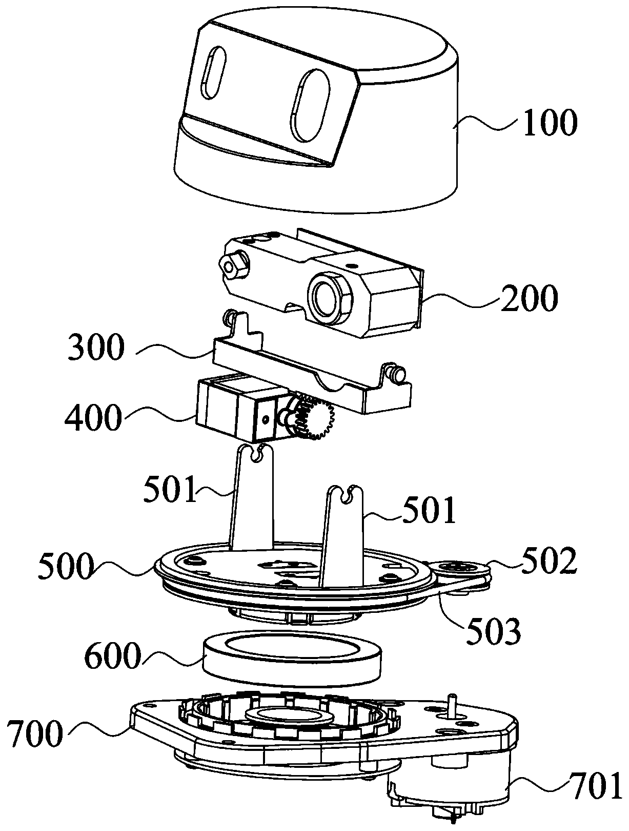
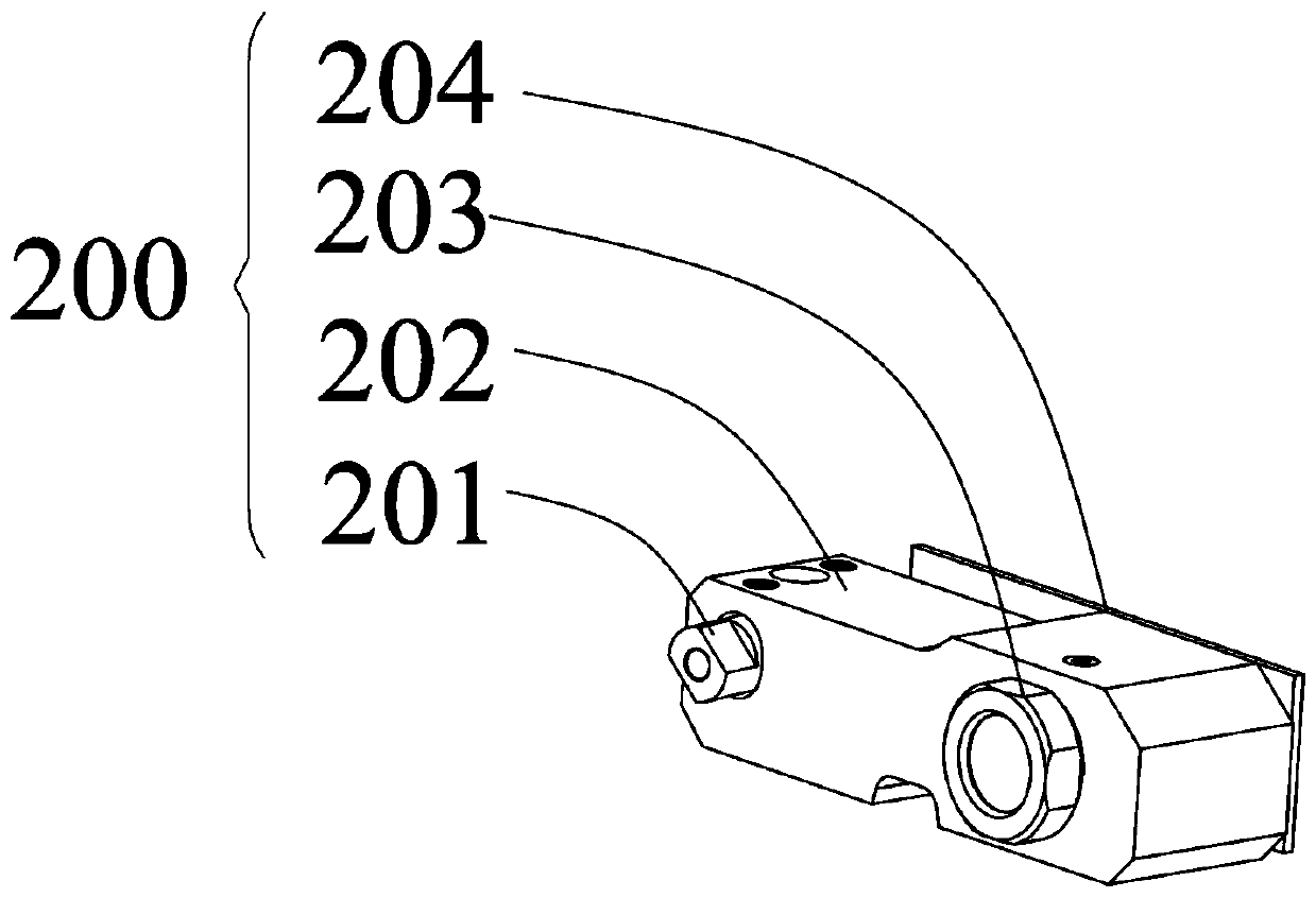
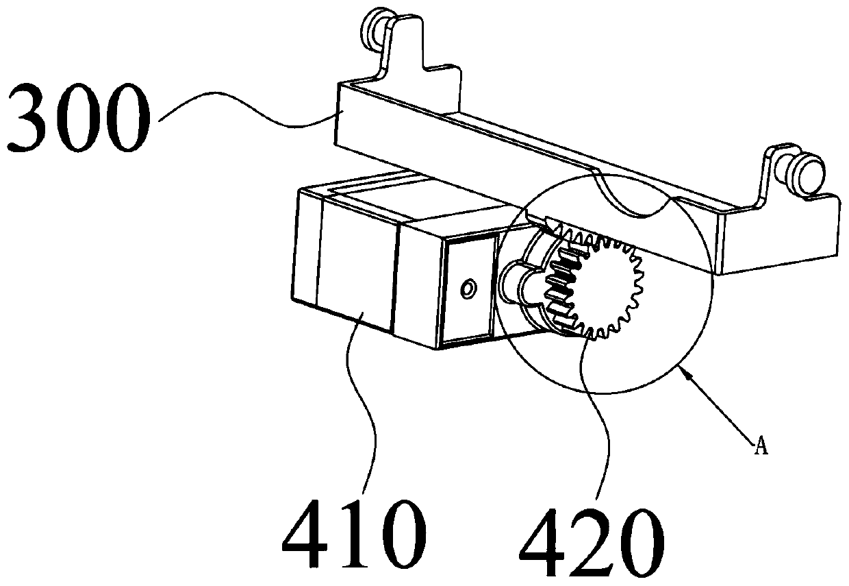
The invention provides a lidar device and a mobile robot. The lidar device comprises a lidar sensor, a rotating platform and a base. The lidar sensor is arranged above the rotating platform. The baseis used for bearing the rotating platform. An adjustment device is arranged between the lidar sensor and the rotating platform. The adjustment device is configured to drive the lidar sensor to rotatearound a first axial direction, wherein the first axial direction is parallel to the rotating platform. The adjustment device is arranged between the lidar sensor and the rotating platform so that thelidar sensor can be adjusted in the vertical direction to realize scanning in three-dimensional space, the scanning range of the lidar device is wider, other lidar devices are not required, the manufacturing cost is obviously reduced in comparison with the multi-line lidar device, and the technical problems of small scanning range of the single-line lidar device and high manufacturing cost of themulti-line lidar device in the prior art can be overcome.

Description

technical field [0001] The invention relates to the field of laser radar, in particular to a laser radar device and a mobile robot. Background technique [0002] Lidar Light Detection and Ranging, referred to as LidAR, uses laser beams as the information carrier, and Lidar is a radar system that emits laser beams to detect the position, speed and other characteristic quantities of the target. Send a detection signal (laser beam) to the target, and then compare the received signal reflected from the target (target echo) with the transmitted signal, and after proper processing, you can obtain the relevant information of the target, such as target distance, azimuth , height, speed, attitude, and even shape parameters, so as to detect, track and identify aircraft, missiles and other targets. Lidar generally consists of a laser transmitter, a laser receiver, a rotary table and an information processing system. In recent years, the application of lidar in unmanned driving and mo...

Claims


Application Information

Patent Timeline
IPC IPC(8): G01S7/481G01S17/93B25J11/00
CPCG01S7/4817G01S17/93B25J11/00
Inventor 黄荣育梁飞渡闫瑞君叶力荣张国栋
Owner SHENZHEN SILVER STAR INTELLIGENT TECH CO LTD
Learn More