Optical signal-to-noise ratio measurement method and optical signal-to-noise ratio measurement system

A technology of optical signal-to-noise ratio and measurement method, which is applied in the field of communication, can solve the problems of large measurement error, difficult optical fiber link, high cost and complexity, and achieve the effect of low cost and high precision

Inactive Publication Date: 2019-11-22
WUHAN POST & TELECOMM RES INST CO LTD
View PDF7 Cites 6 Cited by
  • Summary
  • Abstract
  • Description
  • Claims
  • Application Information

AI Technical Summary

Problems solved by technology

Among them, the scheme based on signal statistical moment and error vector magnitude needs to be carried out after the digital signal processing of the coherent receiver, the cost and complexity are high, and it is difficult to realize in the middle node of the optical fiber link; the delay interferometry technology and spectrum sampling technology have low cost , The advantage of sampling at the intermediate node, but when the bandwidth of the signal and noise is similar, the measurement error is large

Method used


Image

  • Optical signal-to-noise ratio measurement method and optical signal-to-noise ratio measurement system
  • Optical signal-to-noise ratio measurement method and optical signal-to-noise ratio measurement system
  • Optical signal-to-noise ratio measurement method and optical signal-to-noise ratio measurement system

Examples


Embodiment Construction

[0038] The present invention will be further described in detail below in conjunction with the accompanying drawings and specific embodiments.

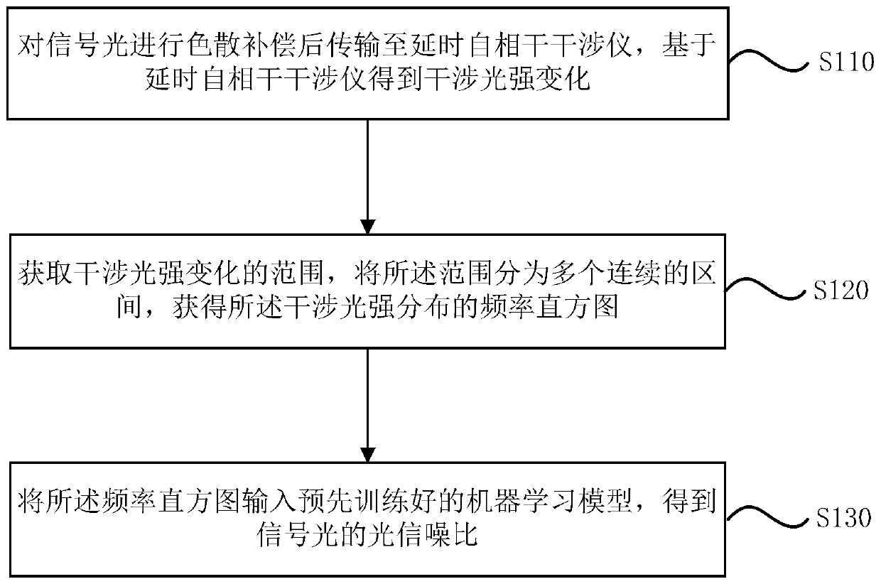
[0039] figure 1 is a flow chart of an optical signal-to-noise ratio measurement method provided by an embodiment of the present invention, figure 1 The method may include steps S110-S130, and the steps S110-S130 will be described in detail below.

[0040] In step S110, the signal light is subjected to dispersion compensation and then transmitted to a time-delayed self-coherent interferometer, and a change in interference light intensity is obtained based on the time-delayed self-coherent interferometer.

[0041] It should be understood that performing dispersion compensation on the signal light is to compensate the dispersion introduced by the signal light during transmission.

[0042] At the same time, the inventors have found through research and experiments that the delay difference between the two arms of the delayed self-cohere...


PUM


Abstract

The invention relates to the field of communications, and particularly discloses an optical signal-to-noise ratio measurement method. The method comprises the steps of conducting light dispersion compensation on the signal light, then transmitting the signal light to a delay self-coherence interferometer, obtaining interference light intensity changes based on the delay self-coherence interferometer, wherein the delay difference between two arms of the delay self-coherence interferometer is larger than the code element period of signal light transmission signals; obtaining an interference light intensity change range, dividing the range into a plurality of continuous intervals, and obtaining a frequency histogram of interference light intensity distribution; inputting the frequency histogram into a pre-trained machine learning model to obtain an optical signal-to-noise ratio of signal light; meanwhile, the machine learning model is obtained by training a plurality of groups of frequency histograms with known optical signal-to-noise ratios and corresponding optical signal-to-noise ratios as a training set, optical signal-to-noise ratio monitoring can be realized at a receiving end and a link node, the measurement precision is higher, and the influence of signal and noise bandwidth changes is not easy to occur.

Description

technical field [0001] The invention relates to the field of communication technology, in particular to a method and system for measuring an optical signal-to-noise ratio. Background technique [0002] In future long-distance, high-capacity, reconfigurable optical fiber communication systems, the link impairments experienced by signals will exhibit dynamic characteristics. Real-time and accurate link characteristic monitoring technology is the key to maximize the use of existing system resources to achieve maximum signal capacity and longest distance reliable transmission. [0003] The optical signal-to-noise ratio is one of the key parameters that determine the performance of optical signal transmission, and it determines the bit error rate of the system to a large extent. Therefore, OSNR monitoring is one of the key technologies for performance monitoring of optical fiber communication systems. [0004] Existing techniques for realizing optical signal-to-noise ratio meas...

Claims


Application Information

Patent Timeline
Patent Type & Authority Applications(China)
IPC IPC(8): H04B10/079
CPCH04B10/07953
Inventor 冯其光李蔚余少华
Owner WUHAN POST & TELECOMM RES INST CO LTD
Why Eureka
Try Eureka