Protective device for punch

A protection device and stamping machine technology, applied in metal processing equipment, safety equipment, manufacturing tools, etc., can solve problems such as injury to workers, finger cutting, safety hazards, etc., to reduce risk costs, improve work efficiency, and protect personal safety. Effect

Pending Publication Date: 2019-11-26
芜湖明达汽车座椅有限公司
View PDF0 Cites 2 Cited by
  • Summary
  • Abstract
  • Description
  • Claims
  • Application Information

AI Technical Summary

Problems solved by technology

[0005] Aiming at the deficiencies of the prior art, the present invention provides a protection device for a punching machine, which solves the problem that there is a great potential safety hazard in each punching process of the punching machine. When shifting, they will subconsciously use their hands to straighten it. Once the worker puts his hand into the center of the punch press, the finger will be severed, and the entire finger will be cut off. In addition, the punch sometimes has workpiece positioning errors, and the workpiece is removed from the punch during processing. In the case of being jumped out, thereby injuring the workers, causing serious consequences

Method used


Image

  • Protective device for punch
  • Protective device for punch
  • Protective device for punch

Examples


Embodiment

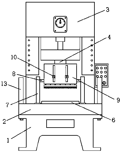
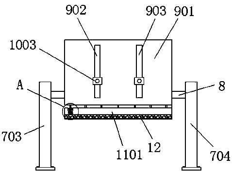
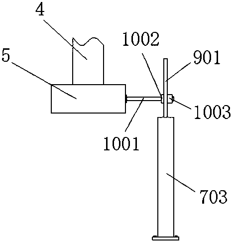
[0029] Such as Figure 1-6 As shown, the embodiment of the present invention provides a protection device for a stamping machine, including a stamping machine tool 1, a workbench 2 is arranged at the center of the stamping machine tool 1, and a power unit 3 is provided on the top of the stamping machine tool 1, and the power unit 3 is used to control the stamping process. The telescoping of the rod 4, the bottom of the power unit 3 is provided with a stamping rod 4, the bottom of the stamping rod 4 is fixedly connected with a stamping block 5, the center of the top of the worktable 2 is provided with a workpiece placement plate 6, and the front end of the top of the workbench 2 is provided with a reset Mechanism 7, the center of the reset mechanism 7 is slidingly connected with a partition mechanism 9, a connecting mechanism 10 is provided between the stamping block 5 and the partition mechanism 9, a buffer mechanism 11 is provided at the bottom of the partition mechanism 9, an...


PUM


Abstract

The invention provides a protective device for a punch and relates to the technical field of punch protection. The protective device for the punch comprises a punching machine tool. A workbench is arranged in the center of the punching machine tool. A power device is arranged at the top of the punching machine tool. A punching rod is arranged at the bottom of the power device. A punching block isfixedly connected to the bottom of the punching rod. A reset mechanism is arranged at the front end of the top of the workbench. A separation mechanism is slidably connected to the center of the resetmechanism. A buffer mechanism is arranged at the bottom of the separation mechanism. A sponge block is arranged at the bottom of the buffer mechanism. The simply designed mechanical protective deviceis used and is matched with an optical grating protective device, thus double protective effects can be achieved, under the circumstance of a failure of an optoelectronic device, a very good protective effect can still be achieved on workers through the mechanical protective device, work efficiency is improved greatly, and meanwhile risk cost of the workers and a manufacturer is also lowered greatly.

Description

technical field [0001] The invention relates to the technical field of punching machine protection, in particular to a protection device for a punching machine. Background technique [0002] The stamping machine drives the flywheel through the motor, and drives the crank linkage mechanism through the clutch and the transmission gear to move the slider up and down, and drives the drawing die to form the steel plate. The flywheel drives the gear, crankshaft (or eccentric gear), connecting rod, etc. to run through the clutch to achieve the linear motion of the slider, and the movement from the main motor to the connecting rod is a circular motion. [0003] The main function of the punching machine is to stamp the sheet metal. Every time the punching machine is punching, there are great safety hazards. When the worker finds that the position of the workpiece to be processed is shifted on the punching machine, he will subconsciously Use your hands to straighten it. Once the work...

Claims


Application Information

Patent Timeline
Patent Type & Authority Applications(China)
IPC IPC(8): B21D55/00B21D22/02
CPCB21D22/02B21D55/00
Inventor 毛明光吴亨玉尹梅孙向成戴涛王宝国宋金成宛宏宇崔玉龙
Owner 芜湖明达汽车座椅有限公司
Why Eureka
Try Eureka