Internal combustion horizontal rotary continuous carbonization furnace

An internal combustion horizontal carbonization furnace technology, which is applied to coke ovens with horizontal carbonization chambers, rotary carbonization furnaces, coke ovens, etc., can solve the problems of low manufacturing cost and blockage.

Pending Publication Date: 2019-11-26
吉林省金福一农业科技有限公司
View PDF0 Cites 5 Cited by
  • Summary
  • Abstract
  • Description
  • Claims
  • Application Information

AI Technical Summary

Problems solved by technology

[0003] The object of the present invention is to provide an internal combustion horizontal rotary continuous carbonization furnace in order to solve the above problems. The material in the present invention enters through the feed port, and the deflector on the inner drum below the feed port transports the material to the gap between the inner drum and the outer drum. In the interlayer, the inner drum introduces a heat source to heat the materials in the interlayer of the inner drum and the outer drum, and the motor is used to drive the inner drum and the outer drum to rotate. The deflector in the interlayer conveys the material to move forward. When the material is heated and carbonized, combustible gas is generated. The combustible gas is introduced into the inner drum, and air is introduced into the inner drum, and the combustible gas is burned in contact with oxygen to form the recycling of the combustible gas during the carbonization process. With this design, the carbonization process generates combustible gas and vaporized tar when the material is heated and carbonized. Introduce the combustible gas and vaporized tar into the inner drum, and pass air into the inner drum to burn them. It is used as a heat source for carbonized materials, forming energy recycling, and solving the problem that the flue is blocked by tar. The heat source is set at The inner drum prevents the drum from being deformed by high temperature, and the sealing is strict during the carbonization process of the material, the carbonization rate is high, the structure is simplified, the failure rate of the equipment is reduced, and the manufacturing cost is low, which solves the shortcomings of the existing technology

Method used


Image

  • Internal combustion horizontal rotary continuous carbonization furnace
  • Internal combustion horizontal rotary continuous carbonization furnace
  • Internal combustion horizontal rotary continuous carbonization furnace

Examples


Embodiment Construction

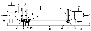
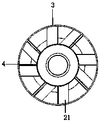
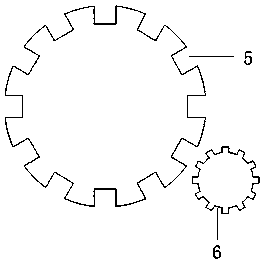
[0020] Such as Figure 1-3 As shown, this specific embodiment adopts the following technical scheme: an internal combustion horizontal rotary continuous carbonization furnace, including a feed end 1, and a feed port 2 is fixedly connected to the feed port 1, and the feed port 2 is connected to the feed port 2. The ends 1 are connected to each other, and an inner drum 4 is inserted inside the feed end 1 below the feed port 2, and an outer drum 3 connected coaxially is set on the outside of the inner drum 4, and the inner drum 4 is connected to the outer drum. Between the outer walls of the drum 3 is a material carbonization space, and a number of deflectors 21 are welded between the inner drum 4 and the outer drum 3, and a number of fixing plates 10 are arranged on the outside of the outer drum 3, and one side of the fixing plate 10 It is fixedly welded with the outer drum 3, and the fixed plate 10 is fixedly connected with a large gear 5 on the other side of the outer drum 3, ...


PUM


Abstract

The invention discloses an internal combustion horizontal rotary continuous carbonization furnace. The furnace includes a feeding end, which is fixedly connected to a feed inlet, and the feed inlet and the feeding end are intercommunicated. The invention has the beneficial effects that: a combustible gas can be generated when a material is heated and carbonized, the combustible gas is guided intoan inner roller, in which air is also introduced, and the combustible gas contacts oxygen and combusts, thus forming cyclic utilization of combustible gas in the carbonization process, according to the design, in the carbonization process, the material is heated and carbonized to generate combustible gas and vaporized tar, the combustible gas and vaporized tar are both introduced into the inner roller, in which air is also introduced for combustion to provide a heat source for material carbonization, thus forming cyclic utilization of energy sources, and solving the problem of flue blockage caused by tar, the heat source is disposed in the inner roller, and can prevent deformation of the roller at high temperature, in the material carbonization process, the furnace is sealed strictly, thecarbon yield is high, the structure is simple, the equipment failure rate is reduced, and the manufacturing cost is low.

Description

technical field [0001] The invention belongs to the technical field of biological carbonization, in particular to an internal combustion horizontal rotary continuous carbonization furnace. Background technique [0002] Existing carbonization equipment generally uses a heat source to heat the furnace cylinder externally, and the straw undergoes high-temperature anaerobic pyrolysis and carbonization in the furnace cylinder. However, the furnace body undergoes high-temperature deformation, resulting in a decrease in equipment operation accuracy and a high failure rate, and the two ends of the furnace body are not tightly sealed. , The biomass is not really cracked in the anaerobic state, which increases the ash content of the charcoal, resulting in a low charcoal yield. Therefore, the present invention proposes a new type of internal combustion horizontal rotary continuous carbonization furnace. Contents of the invention [0003] The object of the present invention is to prov...

Claims


Application Information

Patent Timeline
Patent Type & Authority Applications(China)
IPC IPC(8): C10B1/10C10B5/00C10B53/00
CPCC10B1/10C10B5/00C10B53/00
Inventor 程海荣王伟尚春民
Owner 吉林省金福一农业科技有限公司
Why Eureka
Try Eureka